THIS BLOG HAS MOVED. PLEASE UPDATE ANY BOOKMARKS TO GO DIRECTLY TO WWW.RAISINGGEEKS.COM

Friday, September 03, 2010

September 3rd: First big welding project is complete!

The family worked together to make a planter for my mother-in-law, Elaine. My boys call her "Nana", so we personalized the planter with the new plasma cutter.


We made an upright "trellis" out of steel square tube, 1/4" plate and some cut mounting hooks from IKEA.


Primed the galvanized metal, cleaned the bare steel, and then painted the whole thing...


If you are paying attention, you are wondering - "what is that little yellow box next to the planter?" - Great question! :)

After we had "NANA" cut in the side of the planter, I thought...OOOOH...why not BACKLIGHT it so that at night you see this...


Back at Home Depot, I grabbed a 3-LED solar landscape light and then brought it home to disassemble. That little yellow box is the "light box" which holds the LEDs and has the attached solar panel.

The final product (with a Jasmine plant installed) looks like this...and at night, "NANA" is visible through the side just like the pic above...


Here's another shot where you can see the light...


It also has some ACCESSORIES! First a bright purple watering can (she loves purple)...


And I found this idea online, so the boys & I made one from spoons and a ladle we purchased at IKEA.


The family is very proud of how it turned out, everyone had a chance to help in some part of the construction, and we think she will LOVE it. Her cake is also a planter / flower theme, so it all works together!

Below are some pictures of the light box construction. It was great sheet metal fabrication practice for me...


This is the light box in the middle of welding the curved edges. The light box started as a flat sheet of 22 gauge sheet metal from Home Depot. Adam & I made a template with cardboard, then used the plasma cutter to cut it out, then the vise for bending the edges, then tack welded & grinded the seams...


This is the point where I really got excited - the edges came out GREAT and I never thought I could build something like this...


You can see some of the little holes...more welding & grinding required!


Once it was painted, I moved to the workbench for assembly...


I drilled the big hole in the back after painting, which meant another prep / paint / wait cycle...Next time I build something like this I'll fine sand it after priming and between top coats. I experimented a bit with it on this one and that section came out ultra-smooth!


The remaining parts from the sacrificial landscape light. I picked this one due to 3 LED brightness, a BIG solar cell and a lithium battery. I was surprised to see 5 wires going to the LEDs. The charging circuit is down on the board with the LEDs.


Below was a test fit with the new aluminum reflector. Blue tape is so versatile! Here it is attaching the board AND insulating it from the aluminum reflector :)


I used ribbon cable to extend the wires, and heat-shrinked everything :) I also used hot glue to insulate the back of the circuit board AND to attach the board to the reflector.


I bent a piece of clear polystyrene and siliconed it to the the front of the box to both waterproof and diffuse the light. I did not trust my welded seams to be waterproof so I siliconed all the edges :) Messy, but should be watertight.


In the front view of the final light box, you can see the aluminum reflector (it is curved...looked cool, don't know if it really helps...) and the LED / charging circuit and wires hot glued to the reflector...


Another benefit of this light is that the battery is replaceable and in the bottom of the solar cell assembly, so I don't have to open the light box...


This was a GREAT project. We plasma cut, bent metal, welded metal, grinded (ground?!), soldered, hot glued, sanded, wire brushed, primed, painted, heat formed (polystyrene), epoxied (trellis to pot), glued (pvc) and siliconed. 


Monday, August 16, 2010

August 16th: Arduino Tips...

A few quick tips that I wish I'd learned sooner.

1) You can attach a button / switch to an arduino without an external resistor. You connect one side of the button to ground, the other to the digital input. Set the pinMode to input, then turn on the internal pullup resistor using the digitalWrite function. I like using defines for my pin numbers at the top of my file.


  #define SWITCH1         5


  pinMode(SWITCH1, INPUT);
  digitalWrite(SWITCH1, HIGH); //turn on pullup


Later, when you need to read the switch, just use digitalRead and test for LOW.

 if (digitalRead(SWITCH1==LOW))
    {
      //do something
    }

This method simplifies your circuit AND keeps you from running power to all your switches reducing the possibility of shorting your power supply.
 
2) You can use the analog input pins A0-A5 as digital inputs! Just number them 14-19 and use them for standard digital I/O.

Using the above code, you would simply define SWITCH1 as 14 and connect the switch to pin A0 on the arduino...

  #define SWITCH1         14 //A0

  pinMode(SWITCH1, INPUT);
  digitalWrite(SWITCH1, HIGH); //turn on pullup
 

Little tips go a long way to maximizing productivity and hardware capability...enjoy!

Sunday, August 15, 2010

August 15th: Hockey Season!

My good friend Luis is a bit of a Hockey nut. He not only watches hockey (He's a Rangers fan...), he pre-plays the games for the Rangers on his xbox with his brother. He also has an "original 6" table hockey game with a custom cover made by his family.

I don't think that is the exact model, but you get the idea :)

A few years ago, I was scrapping an old air hockey table and Luis took  the scoring system and modified his table hockey game to use the scoring mechanism.

He cut out the goal area so the puck could go down into custom lexan fixtures that hold the air hockey table scoring switches.


These velcro to the bottom of the table hockey game. They are removable so the table can be transported and still lay flat.

Last year when I got into messing with arduinos, we were kicking around the idea of making a custom scoreboard for the table that would use the Adafruit WaveShield to play hockey arena sounds & music.

At the time I wrote out some basic plans, but focused on finishing my son's "control panel" and finishing my MBA.

A month or so ago, I found the NCR VFDs at Skycraft and this triggered the scoreboard idea again. I made a shopping list for Luis, he ordered the parts and off we went.

The project has come together quickly. We had an afternoon where we soldered up the WaveShield and modded his VFD for TTL serial. I have worked on the code a few hours here & there, and Luis has been working on getting the components mounted. Since I didn't have my shiny new welder this week (thanks UPS - once again you screw with my happiness!) I decided to really get moving on this project. I wrote most of the code logic yesterday and today we got the prototype case finished up. 


Here is the VFD mounted in the case. We had a little mix-up on the VFD dimensions, so the prototype has a little extra view of the VFD :)


Side view showing the lighted power button and power jack


A shot of the inside wiring - Arduino and WaveShield on the bottom right, VFD is the big board, buttons up top. We've since added an RJ45 "magic jack" with a SparkFun breakout board at the bottom. It will be the connection to the table switches and LEDs. The green wire coming up the middle of the VFD board is the TTL mod. 


.  So, how will this thing look in action?? Here it is next to the table. The wires on the side of the table are where the scoring / intermission LEDs will be placed.


And more action shots...


Intro screen...music will be playing...


Select the home team. The middle button is "next" and the right button is "ok" in this mode.


We are making the periods 20 mins like "real" hockey, but then making the clock run down faster. Not sure it will stay this way, but makes life much easier for testing because I can set the scale at a crazy high number and get periods that are a few seconds long :)


In game shot... (scoring switches not connected yet...) During the game, the right button is "play / pause". After a goal, the timer automatically pauses and then a button is hit to resume gameplay (after a short timer to allow the person hitting the button to "ready" themselves...)


I'm really excited to get the sound / music code integrated and get this thing connected to the table. I might even have to learn how to play!

Sunday, August 08, 2010

August 8th: Let's WELD!

I've backed off the electronics design & testing for the last two weeks. I was in deep and needed a break. I've switched gears to disassembly on the Firebird. I've gone MUCH farther than I intended (as usual) and will likely keep going.

One of the next major projects on the Firebird is rectifying the swiss cheese firewall. The no-longer needed hole for the factory AC is a mess. It had been hacked in the past and the cover plate was gooped on. It wasn't panel bonded or epoxied, it was soft, pliable black goop. Yuck.

I want to do it right, so I've ordered a filler panel from Detroit Speed (this is a common modification since aftermarket AC doesn't go through the firewall) and now I'm learning to weld. Sure, I could use 3M panel bond, but what fun is that?!

Here are two pics of the major firewall hole...


I also have some transmission tunnel cleanup work to do. I've started it with the cheap Harbor Freight flux core box, but I'll wait for the real MIG box to show up before finishing it.

This is the "cover" the previous owner made to patch up the transmission tunnel.


He not only hacked the tunnel, he left a ridiculous amount of holes...


Here is the "after" shot from me filling (and grinding, and filling and grinding...) the holes...


And the new "cover" made from 16 gauge steel...


As usual, I'm trying to get the boys engaged in the process. I don't think they understand yet just how cool welding is. My little guy went shopping for supplies last night AND he watched the GMAW (MIG) WIRE FEED video I purchased.

Here he is, ready for action!


When I took him to the Lincoln Electric site to show him the welder I ordered, he saw that they make an Iron Man welding helmet. I didn't have much choice on the design of my new helmet after that. I suspect I'll have to fight him for it :)


For those of you that are into such things - I've ordered a Lincoln Weld Pak 180, which is a 220v MIG welder. I also ordered the spool gun for welding aluminum and a cart. I will be purchasing an Argon / CO2 mix cylinder for welding steel and a pure Argon cylinder for welding aluminum. Yes, I know TIG is the fancy way to weld aluminum, but this was an easier (and cheaper) way to get started. I need to prioritize my ability to easily weld old steel bodywork and MIG is the way to go for bodywork. If I get decent at this, I'll try TIG in the future.

I also think it will be MUCH easier to teach the boys MIG.

Wish me luck!

Saturday, July 24, 2010

July 24th: General Update

Last weekend I received the BTS550 and BTS555 High Side Switches from Infineon. As usual, my comprehension of the datasheet prior to ordering didn't really prepare me for what I ordered. I missed that these are NOT microcontroller friendly devices. When they are OFF, the voltage at the microcontroller input is the car  power voltage, so thats 12+ volts. Good thing I was using the Rugged Circuits Gator+ and not a standard Arduino, or I would have taken out some pins. The BTS could handle more current, but still not enough to drive the big fans with just one device and a smallish heatsink.

That evening of tinkering was a pretty big setback and I ended up pretty discouraged. If only they made the IPS6011 with a higher current capability. Sigh. I took the rest of the weekend off from electronics and continued the garage cleaning. It was VERY productive and I'm almost done.

During the week, I decided to let the project sit in the background, maybe my motivation would return or I'd have some epiphany.

A few things did come to mind:
1) I should be able to gang the IPS6011 for higher current capability. I emailed International Rectifier to see if they had any design considerations for ganging them.

UPDATE - response from IR (on SUNDAY MORNING!!)


Because IPS parts have HEXFET outputs, it may appear possible to parallel them., because as you know the Rds(on) of MOSFETS has a positive temperature coefficient which aides current sharing in parallel part situations. However, with IPS parts there is a practical difficulty as a result of the built-in over current and thermal overload protections. These protections are not built-in to discrete MOSFETS. There will be small differences in the actual Rds(on), the over-current and thermal trip points due to normal parametric spreads in these characteristics between a number of IPS parts. Which means that in an overload situation one part will be inclined to shutdown before the others. With IPS parts the over current protection is reset when the input signal is cycled from on to off to on and over-temperature is automatically reset when the junction temperature cools by around 7*C. With one of the parallel parts shutdown, the total load current will be shared with fewer devices which in turn will carry an increase in current and tend to shutdown in a chain reaction. As the input signal is cycled, every part will try and turn on again. If the input cycling is automatically repetitive with the current overload condition still present, the junction temperatures will tend to rise progressively until the first device shuts down due to over-temperature. Eventually all devices will shut down initially due to over current and ultimately due to over-temperature. The time for all parts to shutdown will be a function of the magnitude of the over-current, the individual device characteristics and the thermal conditions of the application with respect to heat sink ratings and device local ambient temperatures.

We do have many customers using it in parallel.In a parallel configuration of devcies, the major consideration is effective current sharing.Also, as these devices operate with current sense feedback, extensive circuit testing would 
be needed to ensure proper operation. We do not have reference designs / data for such an
application. However, a point to note is that during circuit turn-on, for a slowly ramping 
current (such as for an inductive load), the paralleling works better. For fast ramping loads
paralleling may be more difficult. You would also have to ensure proper feedback for each of 
the devices in parallel.

2) I've been testing with my WORST-CASE load - a GIANT cooling fan. I can always relay these big inductive loads and go on with life. I need to move forward with my plan to measure each load in the car to figure out if a single IPS6011 circuit for each will suffice. With a small heat sink, I proved them for an 18 amp inductive load. With a larger heat sink and a non-inductive load, I may be able to push higher.

3) Big mosfets aren't usually shoved in little cases - in fact, the cases themselves are typically the heatsink - car audio amplifiers and car ECM / ABS modules come to mind - the cases for most car modules are thick aluminum and many have fins molded onto the case. I may hit a "u-pull it" junkyard for some case options...

Last night I finished pulling  the factory harness. I found even more crimp connectors, taped connections and wires to nowhere. The seats are out, the carpet is almost out. I need to pull a few more things, then get started putting Humpty Dumpty back together again. Once again I'm having that "why did I go this far" feeling. I sure like doing this to myself... I need to either get this wiring harness project moving or just order one to move on - but that sure wouldn't be as much fun...or frustration :)

Sunday, July 11, 2010

Vacuum Florescent Display

I picked up one of these displays yesterday at SkyCraft. Someone was nice enough to create a documentation page for them, and has a youtube video example...

Vacuum Florescent Display - TechNet


Update:

After reading the documentation above, I got out a DB9 serial cable and wrote some quick Processing code to test out the VFD. It worked according to spec and I had it cycle through the character sets (including an undocumented third set). Reading deeper into the docs above, I saw the comment about RS-232 to TTL conversion by an onboard IC. Feeling newly empowered by knowledge and tools, I got out the logic analyzer and found the pins that had the TTL serial feeding the display microcontroller. Once I confirmed the pin, I looked for an open test pad to solder to - no such luck. I downloaded the datasheet for the microcontroller, found the rx pin, attached the analyzer and confirmed it had the TTL serial signal. This time, there was an open test pad, I confirmed it had TTL serial, and then soldered a jumper wire from the test pad over to one of the unused pins on the main connector. I got out an Arduino, quickly ported my code from Processing to Arduino and had the same character set scroller running from the Arduino.

So what's ironic is that today I set out to connect this display to an Arduino by building a MAX232 circuit that would convert the Arduino TTL serial to RS-232. I had ordered the wrong capacitors and couldn't build the circuit - but then later in the day, determined the reverse conversion was happening on the VFD and I could just cut out the middle man. I'm no longer upset about ordering the wrong caps - this was a WAY better learning adventure with a better outcome. Learning is fun :)

July 11th: Homemade Solid State Relays...

This week while searching for enclosures for this microcontroller car wiring project (that still needs a name), I had the idea to mount the IPS6011 High Side Intelligent Power Switches inside ISO Micro Relay cases. The micro relays have 5 connections and Delphi makes some great modular enclosures to hold them. Once I arrived home from the beach and the IPS6011s had arrived, I purchased a few micro relays to see if they would fit. Short version - they fit with minimal effort, and can convert an existing micro (coil) relay into an IPS (solid state) relay in about 20 minutes with some practice. You can see the ugly results below. I'm sure there is a better way, but this is the result of my first attempt. So far I've switched and PWM'd a 10 amp inductive load (automotive cooling fan) without any issue - with the top reinstalled. PWM switching of a 10 amp load makes these things HOT. I've had it over 200 degrees Fahrenheit which is still 100 degress below the thermal protection threshold. For now, the only heat sink is the existing coil mounting tab which is also the main power terminal.


Here are some assembly pics...


Some other notes: The diagnostic output works great. I'm using the simple version of the diagnostic circuit which requires no components other than the resistor that is in the relay case (and the internal pull-up resistor in the Arduino circuit).

So far I've run everything off the 12amp bench power supply. The next tests will be off a car battery - I need to test some larger loads, and see if I can hit thermal shutdown. Destructive testing is fun - I'll have the fire extinguisher handy :)

UPDATE:

Full size car battery tests - I can run one cooling fan long term (a 10 amp load) and the temperature stays stable at about 125 degrees. Running both fans (in-rush current over 20 amps, then settles to about 15 amps) causes the temperature to skyrocket (even without PWM) and it hits thermal shutdown (I thought there would be a longer off cycle, it seems to go off, then right back on, generating even more heat - I didn't let it keep going...) and the diagnostic pin DOES pickup the issue. I'm wondering if more heat sink would make the difference...I'm tempted to build my aluminum block relay...

No, I haven't figured out why both fans don't seem to draw 2x the current...something is odd...

In my next Digikey order, I think I'll try some other higher-rated power switches. What is nice about my "modular" concept is that I could use inexpensive switches for smaller loads and more expensive switches for larger loads as needed. The IPS6011 were $4.90 each - and these things go up to almost $11 each. When you plan on 30 of them in a system, that cost adds up fast. I think my next part to try is the Infineon BTS50085-1TMB-ND  - $6.95 each, but rated for 44 amps. It is a 7 pin part, but use 4 pins for the output - which makes a lot of sense. They drop the microcontroller ground, which is interesting - but if it works, its one less connection :)

I'm also tempted to try the Infineon BTS555E3146IN-ND - it is $10.15, but rated for 165 amps. I don't know how that's even possible, but if it could PWM my BIG cooling fans (35amps each...) I'd be very willing to spend the $20 for two of them.

Update - July 12th - those BTS50085's are on backorder - DOH! I'll be getting a few of the BTS555s to play with in the mean time. I also made a billet relay case tonight. I've always wanted to make something out of billet, it was very, very time consuming, but came out...pretty nice. I should have taken some pics but I quickly mounted it to my PCB-mounted IPS6011 as a heatsink to see if it would add amperage capacity at a reasonable heat. Turns out, that in a room with some moving air, it stabilized about 180 degrees with both cooling fans as the load. When I stopped all moving air in the room, it climbed slowly to about 200 and stayed there. I think that is still too hot, but I was encouraged to see that a little bit of aluminum went a long way - before I would run them for about 10 minutes before it would go into thermal shutdown. Tonight I went over 30 minutes before I shut it down to get some sleep. More experimentation to come...


July 10th: More Power!!

I've been annoyed by not having a benchtop power supply for sometime. When I'm working with basic Arduino stuff it isn't a big deal because I get 5v off the Arduino - but when I'm working with 12v control, I'm constantly finding some other wallwart or other source, hacking something together and typically without any regard for safety - for me or the circuit. I've been looking at benchtop supplies online and had picked out a nice Extech, but just couldn't justify the cost. I decided to stop by Skycraft yesterday to see if they had something. I had the choice between a new 30 volt / 3 amp digital meter power supply from some unknown Chinese manufacturer for $130, or a used Extech 382222 15 volt / 12 amp analog meter power supply for $95.

I chose the used, known good manufacturer, analog gauge power supply with MORE POWER!

Right now the Extech is pumping out just over 10 amps to an automotive radiator fan at 13.8v. It is very stable, and handles overcurrent gracefully... 

In my haste to leave the store (due to my 7-year old being mad that I wouldn't buy him this large plastic wheel from whatever), I forgot to buy some banana plug leads...but I found some banana plug adapters in the home stereo connector drawer, so I'm good for now.

I'll likely build a plug in 5v supply so that I can easily have dual voltage - but no big hurry, as I mentioned, my Arduinos all have voltage regulation on them...

Saturday, July 10, 2010

Hey, Lego my Droid, you remote-controlled fiend! (video) -- Engadget

Hey, Lego my Droid, you remote-controlled fiend! (video) -- Engadget

I've been saying for some time that the next generation of hobbyist devices are all the Android smartphones that fall out of use - in a small package you get a CPU, Battery, Display, GPS, Wifi, etc. I'm waiting for someone to release an Android version specifically designed for embedding - a "headless" version more or less. These videos show that we are headed that way...

Friday, July 09, 2010

July 9th: Time to think...about Modular Electrical Centers

Vacation has its benefits - one of which is the ability to clear the mind & think about a topic over a few days. When we are at the beach, I usually have a few hours every morning where others are still asleep, so I go for a walk on the beach. Since Candy is back in Orlando, I haven't been taking the morning walks, but instead sitting on the balcony watching the sun come up while surfing the web. I had some targeted web surfing this week - mostly figuring out how to get this Firebird project moving so I can have the car moving in September as it starts to cool down.

Earlier in the week, my web surfing paid off when I found the MOSFET I needed. This is the most critical part in the whole system - the high-power switching. Once I knew that the IPS6011 would meet my needs, I started thinking about enclosures - specifically the underhood enclosure. I'm not worried about the enclosure for the dash or trunk, since those don't need to be weatherproof to meet my needs. The underhood enclosure has to withstand a good deal of heat, moisture, etc. and ideally, LOOK GOOD. :)

I spent lots of time searching for IP67 rated enclosures and sealed connectors or cable glands. I found a few options, but nothing was really making me happy. I knew that Delphi weatherpak and metri-pak connectors were the way to go for automotive stuff, so I headed to the Delphi site. Once there, I found the catalog I'd seen once before, but had forgotten and I had an AWESOME thought. Modular fuse blocks!


I had to turn my thinking inside out - instead of an enclosure that was sealed and contained the microcontroller (or I2C expander), the 10 IPS MOSFETs and the 10 fuses, why not do the fuses externally. I'd also had this crazy thought for some time - What if I could fit the MOSFET in a fuse housing, then I could just plug them into a fuse block. Unfortunately a fuse only has 2 connections and the IPS MOSFETs need 5. Then it hit me - a Relay has 5 connections. I can make each IPS into a module that is the same size as a relay and they can just PLUG IN. Woah.
My first thought was to buy relays, gut them, install the IPS and any indicator LEDs and reseal them. Seems like a lot of work AND it then looks like a relay when it isn't one. I was also worried about the thermal load of the IPS in that little case. If only I could make the case from aluminum and it would act like one big heat sink. THAT'S IT! I can buy aluminum block, cut to size, drill out for the LED(s) and the IPS and attach the IPS right to the aluminum case. I can use epoxy to "Pot" the IPS and terminals in place. I'm guessing this puts the parts cost of each module at ~$10. For the prototypes, I'll machine them at home, but if it works right, I can see ordering them nicely machined, looking all fancy and mac-book like :) 

Ok, so now I solved for the IPS and for the fuses, but I still need to house the microcontroller or the I2C expander (just called the "control circuit" to make it simpler). Both can fit in very small packages (if ordered with SMT). 

Assuming the use of the 4 module electrical center above, I would have one with mini fuses (bottom left in the pic above), and 2 that hold 6 micro iso relays (not shown). That gives the capacity for 12 fused IPS circuits, and a spot for two extra relays if needed (cooling fans, etc). That leaves space for one more module, which can contain the control circuit. 

I started counting connections...

Connections to "master" = 5
+5v 
Gnd
I2C SCL
I2C SDA
Interrupt request (saves the master polling for diagnostic issues or inputs)

Connections to IPS circuits = 24
1 control line per circuit (lets stick with 12 circuits for now) = 12
1 diagnostic line per circuit = 12 

So for a 12 circuit system, I have 29 connections.

I started looking for connectors, trying to think of how I'd mount the module and the connectors. I kept thinking, "there must be an easy way" - then I realized - the modules that hold 6 relays have 30 connections...hmmm...

Sure enough, I can take the same approach as the IPS. Aluminum enclosure (or plastic since I'm not worried about heat), spades stick out the bottom for all the connections, potted. The entire thing just pushes into the module. I'm a little concerned about removing it with 30 connections, and about getting all those spades mounted right - so I'm not sold on this one yet. There may still be a better way, but I need to get the electrical center here to see it.

What I LOVE about this option, is that it is crazy modular. You can scale the number of circuits up or down very easily. Only need 8 circuits, you only have to make / buy 8 of the IPS modules. Fry an IPS (not sure how given all its internal protection), just pop one out and replace it. If they can dissipate heat properly, I might be able to even put two IPS in one case DOUBLING the current capability (BIG cooling fans with PWM...) Best part is minimal manufacturing, and it should blend into the engine compartment since people are used to seeing these electrical centers and not really giving them a second look. With this design, there are quite a few electrical centers that could be used - just a matter of picking the one that meets your needs.

mouser.com carries all the delphi parts and they can all be ordered by the piece. I priced out the modular center concept above and BEFORE terminals, it is ~$50. I'm guessing I'd spend another $20+ on terminals. While this might seem pricey, I will no longer need a large PCB design...A small and simple PCB for the control circuit is likely all that is needed.

I'm sure there is more to be solved - but at the moment, this feels like a VERY good direction. If it works out well, I can use the same mounting system in other parts of the car - but without the need for the sealing, I may keep it simpler. Then again, this may prove to be the way to go all around...that electrical center is only 7.24" x 4.6" x 1.65"...which would fit well in any of the spaces I'm thinking...


I haven't pulled the trigger on the order yet. All this is contingent on the IPS working the way I need. The IPS order should be at the house today - I'll get them tested, then I'll build one of my micro-relay aluminum IPS modules, make sure it can take the heat - if that all works, I'll order the electrical center and get started on the control circuit mounting. I suppose I should get to work on the actual control circuit, but for some reason that seems "easy" to me once the IPS and weatherproof mounting get solved. I'm sure I will regret thinking that later :)


Thursday, July 08, 2010

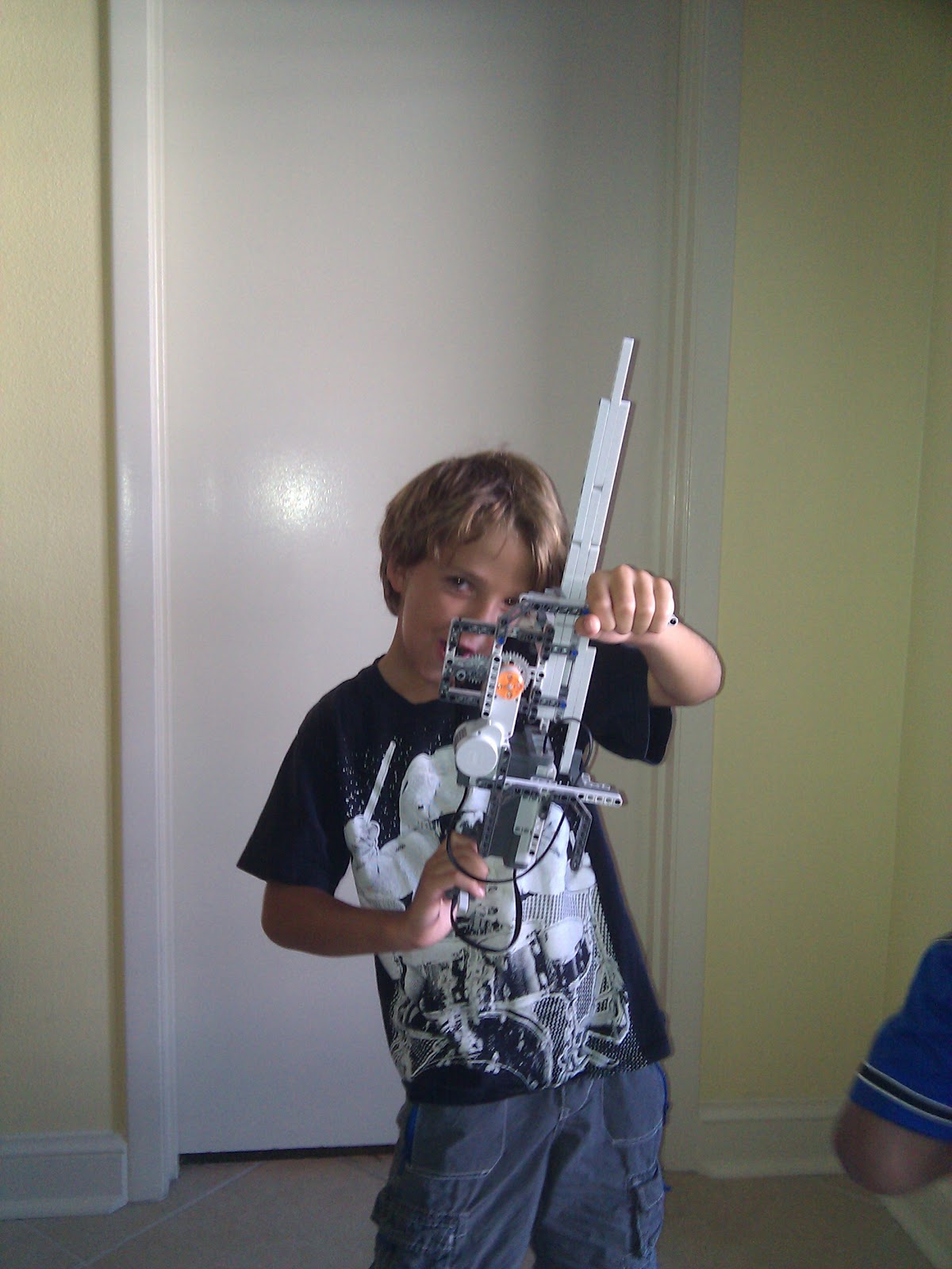
July 8th: Lego Machine Gun

We brought the Lego NXT 1.0 Robot set to the beach with us. After a minor setback (Dad left the CD in the box at home, but when Mom went back, she was able to zip it & send to Dad...), we were operational.

The boys decided they wanted to make the machine gun from nxtprograms.com. We started it last night, then about step 17 decided it was getting late. We finished it today and immediately test fired it. It shoots all 10 "bullets" (three hole technics pieces) in about 2 seconds (as seen in the video below). The boys think it is "AWESOME!"...


Wednesday, July 07, 2010

July 6th: Arduino 3x3x3 LED Cube

I'm keeping the boys entertained at the beach this week. My need for constant stimulation has CLEARLY been passed onto them, so yesterday was an action-packed day. We started the day by building a 3x3x3 LED cube driven by an Arduino. 


I've seen these on youtube, the Arduino forums, Make, Instructables, etc. and have wanted to make one for a while. I reviewed lots of the different instructions and settled on this one from Instructables since it included Arduino animation code.

Before we left for the beach, I made a quick wooden jig on a 2x4 scrap. I created the dot grid using the "Square Dots Graph Paper PDF Generator". I made a 4x4 grid, even though I only intended to build a 3x3 cube. If it worked out, I figured 4x4 was the next logical step and I'd already have the jig :)


After the boys crashed on Monday night, I made the first two layers and setup the Arduino and breadboard so that we could build one layer together, attach it and they could see results almost immediately. For those keeping score, yes, I did bring an Arduino, LEDs, a soldering iron, solder, eye protection, pliers, snips, a breadboard, jumper wires, and alligator clips to the BEACH. It rains a lot here, OK?! :)

The completed 3x3x3 Red LED Cube...the cathodes are all connected together on each horizontal layer and the anodes form the vertical risers. Lighting a specific LED means activating ONLY that cathode layer and that anode riser. The microcontroller does this very quickly and takes advantage of persistence of vision to make it appear that multiple lights are on at one time.


The pics and video don't express the "cool" factor of the 3 dimensional light animation. If I had the patience, I'd build a really large one of these - say an 8x8x8 or maybe even an RGB one - but I don't have the patience to spend a week bending and soldering. I'm surprised I haven't found links yet to buy them presoldered out of China :)

Why would you want an 8x8x8 RGB LED Cube? This video shows how cool they are...


And just in case you were wondering, after building the LED Cube, we went bowling, had lunch, went to Best Buy to get new video games, played the new games for a bit, went snorkeling, threw the Nerf  whistling football on the beach, went grocery shopping, made dinner, played more video games, played tennis, went swimming, played two games of  chess with the large set on the sun deck, played more video games (while Dad did laundry and dishes) and all passed out at 10pm :)  Whew!

Monday, July 05, 2010

July 5th: Seek and Ye Shall Find!

After my first rushed attempt to get MOSFETs for the Firebird microcontroller project that still needs a name (Maybe I should have a naming contest!), I'm taking my time researching to determine the right part. I've been keeping a list of candidate MOSFETs here.

Yesterday, while sitting somewhere, "relaxing", I went on a marathon component web search. I just kept thinking that I couldn't have been the only person trying to solve this problem. I made a list of my "ideal output stage" features:


  • 25 Amp continuous High-Side Switch
  • ATX or Mini-ATX fusing
  • Fuse Blown detection
  • Open circuit detection
  • Short circuit detection
  • Current measurement
  • Transistor Heat detection
  • Logic-level control (safe for microcontrollers)
  • PWM capability for "soft-start" of load
  • Manual override switch in case of microcontroller failure (limp-home mode...)

Given this list, I went searching for circuit designs and components, expecting that I'd use one of the MOSFETs I'd already found plus some extra components to keep the MOSFETs safe.

One of the best ways to find microcontroller-safe circuits is to search with Ardunio or PIC in the search terms. Sure enough I tripped on this post - "MOSFET to drive load, cables". I saw a reference to something called an Intelligent Power Switch. Now THAT sounded like what I was looking for...

Sure enough, I hit the jackpot... Meet the IPS6011...Datasheet

Features
• Over temperature shutdown (with auto-restart)
• Short circuit protection (current limit)
• Reverse battery protection (turns On the MOSFET)
• Full diagnostic capability (short circuit to battery)
• Active clamp
• Open load detection in On and Off state
• Ground loss protection
• Logic ground isolated from power ground
• ESD protection
Description
The IPS6011(S)(R)Pb Switch (IPS) for use in a high side configuration. It features short circuit, over-temperature, ESD protection, inductive load capability and diagnostic feedback. The output current is limited to the Ilim value. The current limitation is activated until the thermal protection acts. The overtemperature protection turns off the device if the junction temperature exceeds the shutdown value. It will automatically restart after the junction has cooled 7°C below the Tshutdown value. The reverse battery protection turns On the MOSFET. A diagnostic pin provides different voltage levels for each fault condition.
The double level shifter circuitry will allow large offsets between the logic and load ground.


Digikey sells the IPS6011 for $5.57 each. While this seems expensive at first, if I priced adding all the other components for thermal protection, logic-level MOSFET driver, etc - this is very reasonable, AND a big space savings. I don't get current measurement (I don't know why I really needed it...) and it is limited to 18A continuous (but has current limiting above 60A, so good headroom for in-rush current), but it looks like the right component!

I then found the application notes for the IPS60xx series - This thing is DESIGNED for my application - switching automotive loads! The application notes explain what happens if you disconnect the battery with the alternator running, if you remove the battery with active inductive loads, etc. I wanted to try to make the system resilient, this thing is perfect.  

Some concerns: 
1) 18A Continuous limit - I really don't think this is a problem since I plan to run most devices discretely - for example, headlights will be split into driving lights, lowbeam and highbeam vs. one circuit that powers all three. This will likely put a fully-loaded car near 30 circuits, which means $167 in just these components. I never said this would be cheap :)
2) PWM - The max switching frequency is listed as 0.3kHz which is 300Hz. The standard Arduino PWM is 500Hz, but a little research showed that the next step down is 250Hz, and there are even lower frequencies. I don't know enough about PWM to know if that would give me soft-start if needed, but it seems promising. 

I need to get a few ordered (Not ordering 50 of these!) and then learn how to use the diagnostic circuit works (you have to "switch-in" two different resistors to find some detailed problem states - not sure if I need to know those specifics, versus just "something not right...")


Friday, July 02, 2010

July 2nd: Logic Analyzer added to the toolkit!


This is a screenshot after playing with the Saleae Logic Analyzer for a few minutes. I attached probes to ground, I2C SCL, and I2C SDA on the microcontroller network and poof, I can inspect the traffic. Above you can see me sending one of the slave microcontrollers a 5 byte command with a 16 bit CRC attached.

I'll be learning how this thing works over the next few days and it should save me lots of debugging when I make silly mistakes. I also hope it will let me hack other devices much faster since I will be able to inspect their I2C, One Wire, or Serial communications :)