I was showing a coworker the latest pics of the car wiring harness project and he used the word "breadboard" referring to my big pegboard project case. I realized I had made a PegBreadBoard! Sure enough, it lets me prototype without making permanent physical connections, just like an electronic breadboard. It has a spacing grid for mounting components, just like an electronic breadboard. I like it!
Here are some recent pics with some components mounted...
The switches are mounted in the top panel with wiring underneath, and the microcontrollers are mounted on the bottom panel, and their interconnect and power wiring (not yet installed in this pic) run underneath the bottom board. The microcontrollers are mounted on thin abs black plastic using industrial velcro, and then the abs panels are bolted to the pegboard grid. Very easily movable if my design changes. The big black cables are the USB connections for programming / logging.
The second abs mounting pad in the center section will be used for the power supply - or that is my current theory anyway.
I currently have power + I2C between the controllers and can run my prior code testing the I2C communications, so I'm back to where I was before - next step is to add code to detect all those switches, then DO something :)
The serial LCDs I ordered still haven't arrived, so I'm chasing them. I'd like to get them on the pegbreadboard for debugging output...
More soon...
THIS BLOG HAS MOVED. PLEASE UPDATE ANY BOOKMARKS TO GO DIRECTLY TO WWW.RAISINGGEEKS.COM
Wednesday, June 23, 2010
June 22 - Getting Organized
My garage is ALWAYS a mess. My hobbies consume lots of space with the tools / parts / half-finished projects all trying to coexist based on my focus at that time.
I've given up trying to find the "big weekend" to clean it out, so I'm working on it an hour a night. Its not AS hot as 2pm on a weekend, so I'm making the best of it.
When I added the new garage, I set it up for car + electrical work. Later, when I thought I was buying a CNC router, I started moving all the car + electrical stuff to the old garage to make room for all the wood stuff in the new garage. I never bought the CNC router, but I also never completely rearranged the garage. I have this really cool shelving system that my father-in-law found in a Time / Life woodworking book. It is ROCK solid and can hold anything - and it runs floor to ceiling. I built the first set 5+ years ago, then last year (or was it two years ago?) I did another wall. I have my power saws / belt sander mounted to these wood shelves, and I slide them out to do work. I take the shelf and clamp it to saw horses - poof, instant wood shop. Here is a visual to help...
With the 2 walls I have 8 sections of these shelves (and have the routed 2x4s to make another few sections). This shelving system is very reasonable to build, very strong (you can stand / jump on a shelf) and will last forever (unlike those #*&% plastic hardware store shelves). If you want the instructions, let me know :)
This weekend I was trying to find a home for my drill press - it was one of my nice craftsman workbenches taking up space, and I didn't want it in that garage. It dawned on me that the shelves could actually be workspaces. So the drill press was moved onto a shelf (not mounted, because I could NEVER slide out that shelf anyway). I also mounted my bench grinder on the left middle shelf (the Ryobi) although I moved the other orange bench grinder and mounted my vise on the back of that same shelf. Now my workbenches are clean, I didn't have to drill holes in the workbenches to have my grinder & vise mounted, and everything fits in space I already had. I still need to find a home for some crap that was on those shelves, but the other shelves clearly aren't space optimized anyway...
Next, I decided I wanted to get my airtools off the main workbench pegboard. I don't use them that often and they were taking lots of space. I realized I had some empty space above my compressor, so I grabbed a piece of geartrack, cut it in half, and poof, my pegboard is clean (of airtools..._)
This also found a use for 4 of the 12 geartrack bins I purchased 3+ years ago, but never used. I also installed another piece of geartrack above the workbench pegboard (about 18" below the ceiling), put the last metal shelf up (yet another item that's been sitting here for years waiting for a use) and put some of my hobbyist kits up on it.
I will keep up this "hour a night" routine for a while to see how far I get, and maybe hit it hard this weekend.
I'm doing all this so that the garage is ready for an intense electronics + car work phase this summer / fall. When the garage is clean and tools / parts are organized, my productivity soars. Now I just need to find a place for a whiteboard out there so I can make a big project list...
My garage is ALWAYS a mess. My hobbies consume lots of space with the tools / parts / half-finished projects all trying to coexist based on my focus at that time.
I've given up trying to find the "big weekend" to clean it out, so I'm working on it an hour a night. Its not AS hot as 2pm on a weekend, so I'm making the best of it.
When I added the new garage, I set it up for car + electrical work. Later, when I thought I was buying a CNC router, I started moving all the car + electrical stuff to the old garage to make room for all the wood stuff in the new garage. I never bought the CNC router, but I also never completely rearranged the garage. I have this really cool shelving system that my father-in-law found in a Time / Life woodworking book. It is ROCK solid and can hold anything - and it runs floor to ceiling. I built the first set 5+ years ago, then last year (or was it two years ago?) I did another wall. I have my power saws / belt sander mounted to these wood shelves, and I slide them out to do work. I take the shelf and clamp it to saw horses - poof, instant wood shop. Here is a visual to help...
With the 2 walls I have 8 sections of these shelves (and have the routed 2x4s to make another few sections). This shelving system is very reasonable to build, very strong (you can stand / jump on a shelf) and will last forever (unlike those #*&% plastic hardware store shelves). If you want the instructions, let me know :)
This weekend I was trying to find a home for my drill press - it was one of my nice craftsman workbenches taking up space, and I didn't want it in that garage. It dawned on me that the shelves could actually be workspaces. So the drill press was moved onto a shelf (not mounted, because I could NEVER slide out that shelf anyway). I also mounted my bench grinder on the left middle shelf (the Ryobi) although I moved the other orange bench grinder and mounted my vise on the back of that same shelf. Now my workbenches are clean, I didn't have to drill holes in the workbenches to have my grinder & vise mounted, and everything fits in space I already had. I still need to find a home for some crap that was on those shelves, but the other shelves clearly aren't space optimized anyway...
Next, I decided I wanted to get my airtools off the main workbench pegboard. I don't use them that often and they were taking lots of space. I realized I had some empty space above my compressor, so I grabbed a piece of geartrack, cut it in half, and poof, my pegboard is clean (of airtools..._)
This also found a use for 4 of the 12 geartrack bins I purchased 3+ years ago, but never used. I also installed another piece of geartrack above the workbench pegboard (about 18" below the ceiling), put the last metal shelf up (yet another item that's been sitting here for years waiting for a use) and put some of my hobbyist kits up on it.
I will keep up this "hour a night" routine for a while to see how far I get, and maybe hit it hard this weekend.
I'm doing all this so that the garage is ready for an intense electronics + car work phase this summer / fall. When the garage is clean and tools / parts are organized, my productivity soars. Now I just need to find a place for a whiteboard out there so I can make a big project list...
Saturday, June 19, 2010
June 19th: Phone Geek Day!
When I woke up this morning, I put on my tshirt with the little green Android on it. I guess I knew it was Phone Geek Day!
- Bought the 10 year old his first phone - a T-Mobile My Touch 3g Slide. Android 2.1 - He's VERY Happy.
- Upgraded the old 2G iphone to 3.x firmware, activated, unlocked & jailbroken. Gave it to the 7 year old for wifi use only. He has a "phone" too, but no calls / text. Basically an iPod touch, but it got me past the phone envy.
- Upgraded Candy's My Touch 3g to 2.1 (cyanogenmod) from 1.6. She gets to catch up on some of the Android features she's been missing.
- Upgraded my old G1 from cyanogen 4.x to cyanogen 5.x (Android 2.2) - it will be the garage phone for when my hands are greasy and I want to check email, search for something or control airtunes. Wifi only - no SIM.
Wednesday, June 16, 2010
June 16th - Expensive Lesson:
I received the MOSFETs from Hong Kong today. I bought 50 of them at $1 each + $5 shipping.
I'd ordered these because I saw them recommended on the arduino forum for switching high amp loads with a microcontroller. I did some research and pulled the trigger to get them here.
I pulled that forum post back up tonight and started thinking about building a perfboard to do some load testing. As I'm looking at the schematic, I realized my basic transistor knowledge missed a rather important item. I couldn't really explain the difference between NPN and PNP before - but now it is crystal clear. NPN allow you to switch GROUND, and PNP allows you to switch POWER. I want to switch power, and I have 50 NPN transistors. Oops...
Now I need to identify another transistor and get them ordered. I think I'll read the "Practical Electronics for Inventors" section on transistors a few more times before I spend more money :)
Update:
I'm using this post to summarize what I'm learning as I head to picking new MOSFETs
1) P-Channel MOSFET since I need to switch power, not ground
2) Low RDS reduces heat
3) I need 25A capability, but it is typically recommended to buy 2x capacity, so near 50A
4) Since I'm working with microcontroller voltage (0-5v) and switching 12-14v, I'll need to use drivers, since the difference in potential would be too high and the MOSFET would always be on. This means I don't need "Logic Level" MOSFETs since I will be using drivers.
Candidates:
1) STP80PF55 - P-channel 55V - 0.016Ω - 80A - TO-220 - $2.67 @ Digikey
2) IRF4905PBF - P-channel 55V - 0.02Ω - 74A - TO-220 - $2.81 @ Digikey
3) FQP47P06-ND - P-channel 60V - 0.026Ω - 47A - TO-220 - $2.26 @ Digikey (Used in the Arduino RC Lawnmower)
Other random notes:
1) You can MULTISELECT digikey filters. DUH. No wonder I've always struggled to find items. DUH.
I received the MOSFETs from Hong Kong today. I bought 50 of them at $1 each + $5 shipping.
I'd ordered these because I saw them recommended on the arduino forum for switching high amp loads with a microcontroller. I did some research and pulled the trigger to get them here.
I pulled that forum post back up tonight and started thinking about building a perfboard to do some load testing. As I'm looking at the schematic, I realized my basic transistor knowledge missed a rather important item. I couldn't really explain the difference between NPN and PNP before - but now it is crystal clear. NPN allow you to switch GROUND, and PNP allows you to switch POWER. I want to switch power, and I have 50 NPN transistors. Oops...
Now I need to identify another transistor and get them ordered. I think I'll read the "Practical Electronics for Inventors" section on transistors a few more times before I spend more money :)
Update:
I'm using this post to summarize what I'm learning as I head to picking new MOSFETs
1) P-Channel MOSFET since I need to switch power, not ground
2) Low RDS reduces heat
3) I need 25A capability, but it is typically recommended to buy 2x capacity, so near 50A
4) Since I'm working with microcontroller voltage (0-5v) and switching 12-14v, I'll need to use drivers, since the difference in potential would be too high and the MOSFET would always be on. This means I don't need "Logic Level" MOSFETs since I will be using drivers.
Candidates:
1) STP80PF55 - P-channel 55V - 0.016Ω - 80A - TO-220 - $2.67 @ Digikey
2) IRF4905PBF - P-channel 55V - 0.02Ω - 74A - TO-220 - $2.81 @ Digikey
3) FQP47P06-ND - P-channel 60V - 0.026Ω - 47A - TO-220 - $2.26 @ Digikey (Used in the Arduino RC Lawnmower)
Other random notes:
1) You can MULTISELECT digikey filters. DUH. No wonder I've always struggled to find items. DUH.
Monday, June 14, 2010
June 14th - More parts ordered...

The same project was also automotive based and had a power supply design that used a different voltage regulator than I am accustomed to using. It is a "low drop out" model (LM2940CT-5.0) that can handle the low voltage conditions during cranking. The power supply design also deals with overvoltage and provides a capacitor that acts like a battery to allow shut-down time in the event of total loss of power. Very cool and highly PRACTICAL. I've ordered the voltage regulator and some other parts necessary to make the power supply (oops, just remembered that I forgot to order the cap...) for when I get to automotive use - that will be some time, but good to know there is a design ready. I included the I2C buffer chips and some sockets in the order. I'm thinking that they can't hurt, so why not have them on hand if needed.
I read about the VDIP2 online, then by chance, my latest read "Practical Arduino" had a project which used the VDIP1 module. Since I'd like to have configuration separate from logging and the VDIP2 has 2 USB ports and was only a few dollars more, I thought "why not?!"
The same project was also automotive based and had a power supply design that used a different voltage regulator than I am accustomed to using. It is a "low drop out" model (LM2940CT-5.0) that can handle the low voltage conditions during cranking. The power supply design also deals with overvoltage and provides a capacitor that acts like a battery to allow shut-down time in the event of total loss of power. Very cool and highly PRACTICAL. I've ordered the voltage regulator and some other parts necessary to make the power supply (oops, just remembered that I forgot to order the cap...) for when I get to automotive use - that will be some time, but good to know there is a design ready. I included the I2C buffer chips and some sockets in the order. I'm thinking that they can't hurt, so why not have them on hand if needed.
Wednesday, June 09, 2010
June 9th: The Project Evolves & my learning continues...
I've started mounting mini switches in the pegboard lid of the project box. I think I'll teach Adam to solder and have him practice on all those switch leads soon :) The pegboard worked out really well since I didn't have to drill any holes, and I get a nice alignment grid...
I've been doing lots of thinking in my "in between time" this week - and "picking the brains" of some people I interact with. I'm using this post to document those thoughts and I'll share some parts I've ordered, as well as some tools / books that I think will increase my learning.
Thinking:
Most of my thinking has been about the "configuration" for a specific car. How will an input trigger lead to output commands on a specific slave? I don't want this logic co-mingled with all the send / receive code on the master, and I'd rather not mess with reflashing the gator+ each time I want to change the behavior of a specific output.
For now, I have an array structure in mind that I think will do the trick.
Example:
Pin 5 on the master is wired to the headlight switch.
Parts:
LCDs - I know I want the master node to have a serial LCD for output of important items, I'm not sure about the slaves. The "control panel" used a bare LCD and took WAY too many I/O pins, so I spent a little more money and ordered serial / I2C 20x4 blue / white displays. I bought 3, even though I may not use them for slaves long term, they are really handy for debug output, so why not have them for now. I will try them in I2C mode, but I'm not sure I want any extra traffic on that bus, so they will likely get connected to the spare UART on the gator+ boards. This way, I have the option.
I2C Buffer ICs - I found these last weekend - the I2C network is working great now, but for future projects, I really like the idea of I2C instead of ethernet over long runs of cat5. I almost ordered them, and was already designing the perfboard in my head when I saw this line - "Breakout board available soon. This board will enable easy remote I2C bus extensions with standard cat-5 cable. With RJ-45 connector, breakouts for unused cable pairs, option for providing remote power and selectable bus pull-up resistors." Perfect. I'll wait for those boards to be available, and if I suddenly have I2C problems on this project, then I'll grab the ICs at that point. This type of learning is so awesome, I just keep adding to the toolbox of components I know exist and I know how to use if needed.
Storage - I want some way to store the car-specific configuration and read that configuration at system startup. I'm looking at several options - SD Card, USB Flash Drive, and EEPROM. SD and USB Flash are easily removable and readable via computer, they also give me storage for logging - BUT they consume lots of precious memory space with the libraries that read / write. It might not be an issue... EEPROM is inexpensive, but not so easy to unplug and connect to the computer to update the configuration. I need to keep thinking on this one to determine a) how important is logging, and b) how would an end user that isn't an arduino coder update their car's configuration...
Tools:
Power Supply - I've been wanting to get a selectable voltage benchtop power supply for some time. I'm sure there are less expensive options, but I'm eyeing this one from SparkFun. Once it cools down a bit, I want to setup one of my garage workbenches properly to be able to work in the garage on this stuff without creating a room full of wires & parts.
Logic Analyzer - The more I'm learning, the more I want to be able to troubleshoot faster and see what is happening at a lower level. Adding tons of debugging Serial.println() statements and reflashing the arduino program gets old fast. I've learned about logic analyzers and want to get the analyzer from Saleae Logic. I think this will also be a great way to learn more and to help my sons see how digital circuits work.
Inexpensive Oscilloscope - Never owned one, always wanted one - this portable o-scope is a great start without spending $2k :)
Books:
I purchased "Make: Electronics - Learning Through Discovery". I think it will be perfect for teaching the boys in a "lab" type setting. The book has a great line on the cover "Burn things out, mess things up - that's how you learn."
I also grabbed "Practical Electronics for Inventors". I've looked at it a few times before, but wasn't ready. Now that I need to go deep into some MOSFET circuits, I'm ready to get more into the theory and try to do it right. Should be a good way to kill some upcoming airport / airplane travel time.
Not a book, but still interesting, I've been reading the Atmel ATMEGA 324p (cpu in the gator+ board) documentation. Now that I've worked with Arduino-compatible boards for a while, it is interesting to see the process schematic and go one level deeper. I might have to get out my microprocessor design book from my Computer Science degree - that was one of my favorite classes. Yes, I am a geek in case that wasn't brutally obvious by now.
I've started mounting mini switches in the pegboard lid of the project box. I think I'll teach Adam to solder and have him practice on all those switch leads soon :) The pegboard worked out really well since I didn't have to drill any holes, and I get a nice alignment grid...
I've been doing lots of thinking in my "in between time" this week - and "picking the brains" of some people I interact with. I'm using this post to document those thoughts and I'll share some parts I've ordered, as well as some tools / books that I think will increase my learning.
Thinking:
Most of my thinking has been about the "configuration" for a specific car. How will an input trigger lead to output commands on a specific slave? I don't want this logic co-mingled with all the send / receive code on the master, and I'd rather not mess with reflashing the gator+ each time I want to change the behavior of a specific output.
For now, I have an array structure in mind that I think will do the trick.
Example:
Pin 5 on the master is wired to the headlight switch.
In the master's main loop(), all inputs are read >50 times per second
A Pin 5 read returns LOW showing that the switch has been turned on (You can switch ground instead of 12v+ so you reduce the possibilities of short circuits under the dash and the size of the wires to switches, etc)
The array is read to locate all rows where the first integer is 5 (for pin 5)
In this case 3 rows are found:
Input Pin, Slave, Command, Var1, Var2, Var3, Var4
[05][01][01][01][07][00][00]
[05][01][01][01][09][00][00]
[05][02][01][01][11][00][00]
So, this means that three commands should be sent (these are hypothetical...)
[05][01][01][01][07][00][00]
Input Pin: 5
Slave: 1
Command: 1 (this is the on/off command)
Var1: 1 (this means turn ON the output pin)
Var2: 7 (output pin 7 is the pin to be turned on, and output 7 on slave 1 are the headlights)
Var3: 0 - parameter not used for this command
Var4: 0 - parameter not used for this command
[05][01][01][01][09][00][00]
Input Pin: 5
Slave: 1
Command: 1 (this is the on/off command)
Var1: 1 (this means turn ON the output pin)
Var2: 7 (output pin 9 is the pin to be turned on, and output 9 on slave 1 is the dash lighting)
Var3: 0 - parameter not used for this command
Var4: 0 - parameter not used for this command
[05][02][01][01][11][00][00]
Input Pin: 5
Slave: 1
Command: 1 (this is the on/off command)
Var1: 1 (this means turn ON the output pin)
Var2: 7 (output pin 11 is the pin to be turned on, and output 11 on slave 2 are the taillights)
Var3: 0 - parameter not used for this command
Var4: 0 - parameter not used for this command
This would be a very simplistic "if input" "do something" without any real logic. My goal sometime soon would be to try to map out the full operation of a car in this structure to see if I need something more fancy. I have another more complex structure in my head that would maintain a state machine and then allow commands that modify the state machine, allow if / then logic, etc. but that might be overkill.
Once I know the size of this array, I can determine if searching it for a high pin number is CPU prohibitive. I may need to add an index to the array and then have a lookup table like
Input Pin, Start Index, End Index
This would allow me to quickly go to the commands for that input pin. However, if the total command list is only 50-100 items, the other array may not be worth the overhead.
This array structure could easily be read from EEPROM, SD Card, etc - which would allow changing of the car's configuration without reprogramming. For now I'll just build have the array setup in code, but it seems like a good way to go. I can't help but feel like I'm reinventing the wheel here with a command structure and array storage, so I need to look around to see what others have done before. For those with automotive knowledge, there are standards for this stuff - my I2C network & messaging is really a simplified CAN. I don't plan to interface this stuff with other hardware, so I figured CAN was overkill.
I've also been considering the power consumption of the 3 gator+ boards since they will be on all the time on a car that doesn't get much use. There is a sleep mode I'll investigate and I may need to switch the LCDs in some way to reduce their power consumption. It may also be possible to leave just the master on and power down the slaves until needed.
Parts:
LCDs - I know I want the master node to have a serial LCD for output of important items, I'm not sure about the slaves. The "control panel" used a bare LCD and took WAY too many I/O pins, so I spent a little more money and ordered serial / I2C 20x4 blue / white displays. I bought 3, even though I may not use them for slaves long term, they are really handy for debug output, so why not have them for now. I will try them in I2C mode, but I'm not sure I want any extra traffic on that bus, so they will likely get connected to the spare UART on the gator+ boards. This way, I have the option.
I2C Buffer ICs - I found these last weekend - the I2C network is working great now, but for future projects, I really like the idea of I2C instead of ethernet over long runs of cat5. I almost ordered them, and was already designing the perfboard in my head when I saw this line - "Breakout board available soon. This board will enable easy remote I2C bus extensions with standard cat-5 cable. With RJ-45 connector, breakouts for unused cable pairs, option for providing remote power and selectable bus pull-up resistors." Perfect. I'll wait for those boards to be available, and if I suddenly have I2C problems on this project, then I'll grab the ICs at that point. This type of learning is so awesome, I just keep adding to the toolbox of components I know exist and I know how to use if needed.
Storage - I want some way to store the car-specific configuration and read that configuration at system startup. I'm looking at several options - SD Card, USB Flash Drive, and EEPROM. SD and USB Flash are easily removable and readable via computer, they also give me storage for logging - BUT they consume lots of precious memory space with the libraries that read / write. It might not be an issue... EEPROM is inexpensive, but not so easy to unplug and connect to the computer to update the configuration. I need to keep thinking on this one to determine a) how important is logging, and b) how would an end user that isn't an arduino coder update their car's configuration...
Tools:
Power Supply - I've been wanting to get a selectable voltage benchtop power supply for some time. I'm sure there are less expensive options, but I'm eyeing this one from SparkFun. Once it cools down a bit, I want to setup one of my garage workbenches properly to be able to work in the garage on this stuff without creating a room full of wires & parts.
Logic Analyzer - The more I'm learning, the more I want to be able to troubleshoot faster and see what is happening at a lower level. Adding tons of debugging Serial.println() statements and reflashing the arduino program gets old fast. I've learned about logic analyzers and want to get the analyzer from Saleae Logic. I think this will also be a great way to learn more and to help my sons see how digital circuits work.
Inexpensive Oscilloscope - Never owned one, always wanted one - this portable o-scope is a great start without spending $2k :)
Books:
I purchased "Make: Electronics - Learning Through Discovery". I think it will be perfect for teaching the boys in a "lab" type setting. The book has a great line on the cover "Burn things out, mess things up - that's how you learn."
I also grabbed "Practical Electronics for Inventors". I've looked at it a few times before, but wasn't ready. Now that I need to go deep into some MOSFET circuits, I'm ready to get more into the theory and try to do it right. Should be a good way to kill some upcoming airport / airplane travel time.
Sunday, June 06, 2010
June 6th - Woodworking!
Today we (both boys & my friend Lou helped in various ways...) built this prototype case for the new project.
The top panel will have a top view of a 68 Firebird, with the major electrical items labeled and an LED for each one indicating that it has power. White LEDs for headlights, RED for brake lights, Yellow for turn signals, etc. Maybe blue for all the other stuff, who knows :)
The top will also have a mock dashboard with an ignition switch (keys & all), a headlight switch (a real one that pulls out for parking lamps, headlamps, and has a rotary dimmer for interior lights...) and a bunch of small switches to activate turn signals, brakes, hazards, windows, door locks, etc.
The bottom panel (it is raised 1/2 inch off the bottom to provide mounting hardware & wiring space underneath) will contain the three microcontrollers and show how the car is divided into the engine compartment controller, the under dash controller and the trunk controller.
Today we (both boys & my friend Lou helped in various ways...) built this prototype case for the new project.
The top panel will have a top view of a 68 Firebird, with the major electrical items labeled and an LED for each one indicating that it has power. White LEDs for headlights, RED for brake lights, Yellow for turn signals, etc. Maybe blue for all the other stuff, who knows :)
The top will also have a mock dashboard with an ignition switch (keys & all), a headlight switch (a real one that pulls out for parking lamps, headlamps, and has a rotary dimmer for interior lights...) and a bunch of small switches to activate turn signals, brakes, hazards, windows, door locks, etc.
The bottom panel (it is raised 1/2 inch off the bottom to provide mounting hardware & wiring space underneath) will contain the three microcontrollers and show how the car is divided into the engine compartment controller, the under dash controller and the trunk controller.
June 6th - It's Alive - Part 2!
After adding the CRC16 checking, I added a button on the master and a test LED on each slave. The master's main loop detects the button press and sends one message (to both slaves) if it is not pressed, another if it is pressed (there is no debounce or state management to reduce messages...). The slaves are watching for a specific command with an on / off parameter and turning that pin on or off based on the parameter. The LEDs are VERY responsive to the switch as you can see in the video.
I let the system run overnight and have logged 3.4M messages with ZERO failures at 84.62 messages per second. :)
June 7th Update: Just crossed 10M messages with ZERO failures at 84.63 messages per second. I'm just letting it run at this point until I start coding again...
June 8th Update: 17M messages, still ZERO failures at 84.50 messages per second (interesting that the rate trended downward just slightly in the last 24 hours.) I doubt I will be coding on the system until next week, so I might just leave it running until then :)
After adding the CRC16 checking, I added a button on the master and a test LED on each slave. The master's main loop detects the button press and sends one message (to both slaves) if it is not pressed, another if it is pressed (there is no debounce or state management to reduce messages...). The slaves are watching for a specific command with an on / off parameter and turning that pin on or off based on the parameter. The LEDs are VERY responsive to the switch as you can see in the video.
I let the system run overnight and have logged 3.4M messages with ZERO failures at 84.62 messages per second. :)
June 7th Update: Just crossed 10M messages with ZERO failures at 84.63 messages per second. I'm just letting it run at this point until I start coding again...
June 8th Update: 17M messages, still ZERO failures at 84.50 messages per second (interesting that the rate trended downward just slightly in the last 24 hours.) I doubt I will be coding on the system until next week, so I might just leave it running until then :)
Saturday, June 05, 2010
June 5: It's Alive!
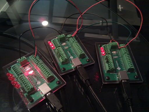
This is a 3 node I2C network with one master and two slaves.
The board with 4 side LEDs is the master. The side LEDs indicate Slave 1 TX / RX and Slave 2 TX/ RX.
The slave side LEDs indicate TX / RX with the master. There is no slave to slave communication.
The on-board LEDs on all boards flash to indicate a heartbeat main loop still running...
The master is sending 5 byte "packets" to each slave, and after it sends, it is requesting a single byte acknowledgement from the slave.
I added some diagnostics last night to indicate pass / fail for each transmission / ack pair. I then went to bed.
8 hours later, I have 4.7M transmissions, with ZERO failed packets at an average rate of 149.66 messages per second.
I am VERY pleased with these results. I've tried to increase the speed by removing code, and the best I can do is ~ 160 messages per second by shortening the packet length. The limiter appears to be the selected I2C bus speed at this point, because transmitting to only one node or both still averages the same messages per second. I don't need more speed, this is responsive enough, I just wondered where the bottleneck might be.
Next step is to try longer wire lengths to see if it works and if it affects speed or reliability.
Update:
After lots of trial & error + googling, I now having the network working over 25 foot lengths of cat 5 (longer than should be needed in an automotive application). For longer lengths, termination resistors (I used 4.5k Ohm) are needed. Once I figured out what to use, I went to longer & longer cable lengths. I can do 3 foot without the resistors, anything longer needs them. I also found some inexpensive ($3) buffer ICs designed for running I2C over long lengths, but at the moment they don't appear to be needed. I'm still powering them all via USB, so next step is to get a 12v power supply connected and try running power & ground over the cat5 as well. I've logged 400k transmissions (5 byte command + 1 byte ack) without failure at ~165 messages / sec with ZERO failures.
I'm very happy with the progress so far - the networking was the part that concerned me most about this concept.
Update - More progress:
I now have CRC16 checksums being added to the outgoing 5 byte command packet. The slave uses this checksum to validate it received the packet correctly, and then as the acknowledgement, sends back the checksum bytes. The master validates the checksum bytes, and the command is believed to have been sent with integrity. This increases a single message to 5+2+2 bytes or 9 bytes total. The increase in byte count and the CRC computation now has the transmission rate down to ~85 messages per second. This is still quite adequate, but I'm hoping it doesn't drop much more as I add input / translate / command send on the master and command receive / translate / output on the slaves. I'll leave it running over night to see a few million messages go through with no error, but at the moment, this seems completely plausible for use in a vehicle.
Monday, May 31, 2010
May 31: The boys and I have a new project.
We have a 1968 Firebird that needs a new wiring harness. I could put in a cheap aftermarket one for $500ish, a really nice aftermarket one for $700, or the new fancy ISIS Power microcontroller-based harness for ~$1500.
I was ready to spend the money on the ISIS system when I realized that while you can buy the "programmer" it just uploads code that you get from the manufacturer. Want to change the operation of the system - you call them, ask nicely and wait for them to send you a .hex file. That is a deal-breaker for me. In the true DIY spirit, I thought - I can build that system! Fundamentally it is the same concept as the "Control Panel" we built before, it just adds the concept of networked microcontrollers to split the output circuits by location in the car.
To get started, I've purchased 3 Gator + boards from ruggedcircuits.com.
They are "hardened" arduino-compatible microcontrollers. Since there are life-safety considerations involved with this adventure I wanted to get boards that were the least likely to fail (or be damaged by me along the way!).
I've got the Arduino development environment loaded & I've uploaded my first simple program to a gator+. Over the coming weeks, the plan is to:
1) Build a reliable wired communication network (I2C?) between 3 nodes (the gator+ boards).
2) Determine the bandwidth of the network so that I can ensure I don't have a delay on a brake light activation for example.
Update - June 1:
I built a 3 node I2C network last night using the wire library examples. I can send hundreds of short (8 byte) messages per second to both nodes. Right now the limiting factor is my serial output of the messages for debugging. This is one-way communication from one master to two slaves.
Next I will try two way communication so that both nodes can send and receive. At a minimum I can use this capability for returning status or warning information to the master. If it worked really well, I could do data logging from all boards.
Update - June 5: Network fully functional - see my newer post...
3) Develop a terse communication protocol and control structure between the nodes.
Update - June 3:
Design considerations floating in my head...
Does the master send "events" and the slaves respond to events OR does the master process the events and send "commands" to the slaves?
What events exist?
What are the "commands" needed?
4) Design / construct a fused output module capable of 20+ amp loads at 12v. I haven't found an output board that fits the bill, so it looks like I will be designing one. The Parallax Digital IO board is the closest I've found, but isn't rated for enough current.
Update - June 4:
I still can't find a ganged power output board that meets my needs, and I think I want to custom design it anyway to be able to have the automotive fuse holders on the board, detect blown fuses, open circuits, overtemp on the mosfets, etc. I'll prototype everything on hand-soldered perf board, and if it works well, I may have some boards professionally made :)
MOSFET selection: I'm ordering the IRLZ44N, based on this arduino forum article. They are technically capable of 47A, but I'm thinking heat management in the TO-220 case will be the actually limiter. I think the failure testing part of the project will be FUN!
5) Build a benchtop test car with all circuits present. Benchtop testing will save LOTS of headaches later.
The boys will be learning all about the electrical system of a car including switches, relays, lamps, etc. I think they will LOVE building a working benchtop car model. I'll probably leave it intact as a testing platform and just order more gator+ boards as needed :)
Stay tuned!
We have a 1968 Firebird that needs a new wiring harness. I could put in a cheap aftermarket one for $500ish, a really nice aftermarket one for $700, or the new fancy ISIS Power microcontroller-based harness for ~$1500.
I was ready to spend the money on the ISIS system when I realized that while you can buy the "programmer" it just uploads code that you get from the manufacturer. Want to change the operation of the system - you call them, ask nicely and wait for them to send you a .hex file. That is a deal-breaker for me. In the true DIY spirit, I thought - I can build that system! Fundamentally it is the same concept as the "Control Panel" we built before, it just adds the concept of networked microcontrollers to split the output circuits by location in the car.
To get started, I've purchased 3 Gator + boards from ruggedcircuits.com.
They are "hardened" arduino-compatible microcontrollers. Since there are life-safety considerations involved with this adventure I wanted to get boards that were the least likely to fail (or be damaged by me along the way!).
I've got the Arduino development environment loaded & I've uploaded my first simple program to a gator+. Over the coming weeks, the plan is to:
1) Build a reliable wired communication network (I2C?) between 3 nodes (the gator+ boards).
2) Determine the bandwidth of the network so that I can ensure I don't have a delay on a brake light activation for example.
Update - June 1:
I built a 3 node I2C network last night using the wire library examples. I can send hundreds of short (8 byte) messages per second to both nodes. Right now the limiting factor is my serial output of the messages for debugging. This is one-way communication from one master to two slaves.
Next I will try two way communication so that both nodes can send and receive. At a minimum I can use this capability for returning status or warning information to the master. If it worked really well, I could do data logging from all boards.
Update - June 5: Network fully functional - see my newer post...
3) Develop a terse communication protocol and control structure between the nodes.
Update - June 3:
Design considerations floating in my head...
Does the master send "events" and the slaves respond to events OR does the master process the events and send "commands" to the slaves?
What events exist?
- External inputs:
- Ignition: On / Off
- Input: On / Off (Do I need to handle expected momentary different than expected latching to keep protocol terse? Don't need to resend stuff over & over)
- Analog Input: Value (Will I have analog inputs for things like interior light brightness, fan temps, or am I sticking with digital?)
- System Events:
- Warning
- Error / Problem
- Critical Failure
- Heartbeat
What are the "commands" needed?
- Standard Outputs
- ON (Output, Max Duration)
- OFF
- BLINK (Brightness, Rate)
- PWM Outputs
- FADE (Start Brightness, End Brightness, Rate)
- PULSE (Start Brightness, End Brightness, Rate, Delay)
- RGB LED (Likely commands are going to separate microcontroller(s) via I2C)
- LED_ON (R, G, B)
- LED_FADE (Can get complicated...)
- LED_PULSE (Can get complicated...)
- LED_CYCLE (Color cycling...very complicated)
4) Design / construct a fused output module capable of 20+ amp loads at 12v. I haven't found an output board that fits the bill, so it looks like I will be designing one. The Parallax Digital IO board is the closest I've found, but isn't rated for enough current.
Update - June 4:
I still can't find a ganged power output board that meets my needs, and I think I want to custom design it anyway to be able to have the automotive fuse holders on the board, detect blown fuses, open circuits, overtemp on the mosfets, etc. I'll prototype everything on hand-soldered perf board, and if it works well, I may have some boards professionally made :)
MOSFET selection: I'm ordering the IRLZ44N, based on this arduino forum article. They are technically capable of 47A, but I'm thinking heat management in the TO-220 case will be the actually limiter. I think the failure testing part of the project will be FUN!
5) Build a benchtop test car with all circuits present. Benchtop testing will save LOTS of headaches later.
The boys will be learning all about the electrical system of a car including switches, relays, lamps, etc. I think they will LOVE building a working benchtop car model. I'll probably leave it intact as a testing platform and just order more gator+ boards as needed :)
Update June 4:
I will be building the test "car" using a top view of the Firebird printed on paper and glued to peg board. I have an enclosure design for the pegboard that gives me two layers of pegboard - the car picture, all indicator lights & switches will be on the top board which will be hinged to allow access to the bottom board. The bottom board will have the microcontrollers & output boards. I plan to make it run from a 12v jumpstarter style battery. I think the boys are going to LOVE building this thing and playing with it. I have it sketched out - I'll get it in diagram form to share soon.
Stay tuned!
Sunday, January 24, 2010
All Hardware Functional!
The Joystick has sound effects (Star Wars & Star Trek sound files on the Waveshield) mapped to the directional axis and some of the buttons. The red button with the flip up cover fires the thrusters (same functionality as the big green button in prior versions) which increases engine temp (as seen on the Engine Degrees gauge) and will cause an overheat alarm if it the temp goes too high.
The Apache Helicopter Data Entry Keyboard now works...the bottom line is for data entry. You get a blinking underline cursor, and the keyboard supports numbers and letters, backspace and enter.
In the future, I'll make it a functional navigation system between Star Wars planets. For now, a little imagination is needed. The three new buttons next to the display are wired, but not mapped to any functionality. I was thinking they would be to select options, with the two black being up & down and the red being enter. Now that the data entry keyboard is functional, I'm not sure what they will be for - but they will find a use!
I seriously underestimated how much wire would be coming into this box. There is a Cat5 cable from the Joystick, two from the Data Entry Keyboard, one from the Left Panel, one from the Center Panel, one from the lid buttons and one from the Liquid crystal. Making the final connections on the Arduino Mega was quite challenging...a much larger box and a Mega screw shield would be much easier...
I also built a 6 volt regulator for the Arduino, which kept all the 12v wiring out of the box. All 12v wiring for the button lamps, siren, and strobe is hidden behind the removable panels.
For the Arduino folks in the crowd...check out this list of pin declarations...I think I used EVERY digital I/O pin on the MEGA - I still have some PWM outputs and some analog inputs remaining...
//WaveShield Pins
//....................2
//....................3
//....................4
//....................5
//analog outputs on PWM pins
#define GAUGE_ED 8
#define GAUGE_LR 9
//Analog Inputs
#define SWITCH_KEYPAD 0
#define JOY_UD_POT 8 //WHITE-BLUE
#define JOY_LR_POT 9 //WHITE-GREEN
//DO NOT USE - Reserved for future I2C or interrputs
//
//....................20
//....................21
//digital inputs
#define BUTTON_RED 22 //WHITE-BROWN
#define BUTTON_YELLOW 24 //GREEN
#define BUTTON_GREEN 26 //WHITE-GREEN
#define BUTTON_UP 28 //WHITE-BROWN
#define BUTTON_DOWN 30 //BLUE
#define BUTTON_ENTER 32 //WHITE-BLUE
//digital outputs
#define LAMP_RED 23 //ORANGE
#define LAMP_YELLOW 25 //WHITE-ORANGE
#define LAMP_GREEN 27 //BLUE
#define SIREN 29 //BROWN
#define STROBE 31 //WHITE-BLUE
//Keypad Col Pins
//....................34 //WHITE-ORANGE
//....................36 //ORANGE
//....................38 //WHITE-GREEN
//Keypad Row Pins
//....................33 //WHITE-BROWN
//....................35 //BROWN
//....................37 //WHITE-BLUE
//....................39 //GREEN
//....................41 //BLUE
//shift.in from joystick
#define SHIFT_CLOCK 40 //ORANGE
#define SHIFT_LATCH 42 //GREEN
#define SHIFT_DATA 43 //BLUE
//LCD pins
//....................44
//....................45
//....................46
//....................47
//....................48
//....................49
//WaveShield SPI pins
//....................50
//....................51
//....................52
//....................53
The Joystick has sound effects (Star Wars & Star Trek sound files on the Waveshield) mapped to the directional axis and some of the buttons. The red button with the flip up cover fires the thrusters (same functionality as the big green button in prior versions) which increases engine temp (as seen on the Engine Degrees gauge) and will cause an overheat alarm if it the temp goes too high.
The Apache Helicopter Data Entry Keyboard now works...the bottom line is for data entry. You get a blinking underline cursor, and the keyboard supports numbers and letters, backspace and enter.
In the future, I'll make it a functional navigation system between Star Wars planets. For now, a little imagination is needed. The three new buttons next to the display are wired, but not mapped to any functionality. I was thinking they would be to select options, with the two black being up & down and the red being enter. Now that the data entry keyboard is functional, I'm not sure what they will be for - but they will find a use!
I seriously underestimated how much wire would be coming into this box. There is a Cat5 cable from the Joystick, two from the Data Entry Keyboard, one from the Left Panel, one from the Center Panel, one from the lid buttons and one from the Liquid crystal. Making the final connections on the Arduino Mega was quite challenging...a much larger box and a Mega screw shield would be much easier...
I also built a 6 volt regulator for the Arduino, which kept all the 12v wiring out of the box. All 12v wiring for the button lamps, siren, and strobe is hidden behind the removable panels.
For the Arduino folks in the crowd...check out this list of pin declarations...I think I used EVERY digital I/O pin on the MEGA - I still have some PWM outputs and some analog inputs remaining...
//WaveShield Pins
//....................2
//....................3
//....................4
//....................5
//analog outputs on PWM pins
#define GAUGE_ED 8
#define GAUGE_LR 9
//Analog Inputs
#define SWITCH_KEYPAD 0
#define JOY_UD_POT 8 //WHITE-BLUE
#define JOY_LR_POT 9 //WHITE-GREEN
//DO NOT USE - Reserved for future I2C or interrputs
//
//....................20
//....................21
//digital inputs
#define BUTTON_RED 22 //WHITE-BROWN
#define BUTTON_YELLOW 24 //GREEN
#define BUTTON_GREEN 26 //WHITE-GREEN
#define BUTTON_UP 28 //WHITE-BROWN
#define BUTTON_DOWN 30 //BLUE
#define BUTTON_ENTER 32 //WHITE-BLUE
//digital outputs
#define LAMP_RED 23 //ORANGE
#define LAMP_YELLOW 25 //WHITE-ORANGE
#define LAMP_GREEN 27 //BLUE
#define SIREN 29 //BROWN
#define STROBE 31 //WHITE-BLUE
//Keypad Col Pins
//....................34 //WHITE-ORANGE
//....................36 //ORANGE
//....................38 //WHITE-GREEN
//Keypad Row Pins
//....................33 //WHITE-BROWN
//....................35 //BROWN
//....................37 //WHITE-BLUE
//....................39 //GREEN
//....................41 //BLUE
//shift.in from joystick
#define SHIFT_CLOCK 40 //ORANGE
#define SHIFT_LATCH 42 //GREEN
#define SHIFT_DATA 43 //BLUE
//LCD pins
//....................44
//....................45
//....................46
//....................47
//....................48
//....................49
//WaveShield SPI pins
//....................50
//....................51
//....................52
//....................53
Thursday, January 21, 2010
I bought this Hughes Helicopter keypad off eBay in 2007 for my son's "control panel" - at the time it looked cool, but I had no intent of trying to use it as an active device. I thought I might use the rotary switch, but not the keypad.
Now that I have an Arduino and I'm learning more & more, I decided to see if I could get the keypad usable...
I traced the circuit and documented all the pins. My son helped me test my pin assignments by continuity testing :)
Last night, I decided I wanted to try to get the keypad working with the Arduino and the keypad library.
I could have put a fancy jack on all that wiring, but why not use solder :)
I used this little board to hold all 20 connections and soldered a piece of cat 5 to the matrix rows & columns.

The keypad library was easy to test, but I got a 0 in between each valid button press. I fought it for an hour before removing the keypad connector - sure enough, there was continuity on the row & column for zero - without the button being pushed. After removing the 20! screws, I determined that the pressure from the back screws was activating the zero button. Put back all 20 screws, and no more false zeros. Unfortunately, no more number one either. Remove all 20 screws again - opps, I guess the #1 button had fallen out the last time and I'd put it in sideways. Reinstall all 20 screws - works GREAT!
I need to put resistors on the rotary switch outputs so I can read them all with a single analog input. I have plenty of analog inputs left, so it seemed better than a shift, although if I chained 2 shifts, I could also pickup the 5 row pins...tempting :)
More later as I reinstall the keypad AND get it to work with the rest of the code on the Mega.
I found a new way to make the "Control Panel" even more interactive.
Last weekend we started hacking the helicopter keypad and once I knew it would work, I asked my son "what can you do in a spaceship with a keypad?" We brainstormed for a while and we came up with the idea of using the keypad for the "nav computer". You type in where you want to go, select the speed, etc.
I started thinking of finding / making some nature of star chart with a coordinate system so that he could see his current location, chart a course, etc.
As I went digging on the net, I found this...
It is a grid-based map of the Star Wars galaxy! It even has zoomed maps of the dense areas...
And an index page!
Original maps here: http://www.xs4all.nl/~wrvh/galaxymap/index.html
Now I get the fun of building a basic navigation system on the Arduino...although probably not right away.
I want to think about it for a little while to let the idea evolve. Send me any comments or ideas you have on the topic!
Last weekend we started hacking the helicopter keypad and once I knew it would work, I asked my son "what can you do in a spaceship with a keypad?" We brainstormed for a while and we came up with the idea of using the keypad for the "nav computer". You type in where you want to go, select the speed, etc.
I started thinking of finding / making some nature of star chart with a coordinate system so that he could see his current location, chart a course, etc.
As I went digging on the net, I found this...
And an index page!
Original maps here: http://www.xs4all.nl/~wrvh/galaxymap/index.html
Now I get the fun of building a basic navigation system on the Arduino...although probably not right away.
I want to think about it for a little while to let the idea evolve. Send me any comments or ideas you have on the topic!
Tuesday, January 19, 2010
Big Milestone!
Houston, we have a CASE!
Something about getting the project into a case makes it feel very real to me. So without further ado, a picture!
I'm made the liquid crystal wiring long enough so that when its mounted on the Control Panel, I can open the lid, move it up, and refasten it so the display is visible and not hanging.
I added the buttons by the LCD to do some basic menu work using the LCD if I choose - up / down / enter will be their likely functionality.
The wiring from the panel will come though the hole between the two top "modules". You can see that better in this picture.
The edge of the Arduino was NOT exposed, since power will come in from the back AND I didn't want the kids pulling out the SD card.
I've also "defragmented" my pin use on the Mega so that I can free some contiguous pins for the 3 new buttons AND something else that is coming soon which I think needs 8 digital pins.
Thanks to my buddy Lou who used his new dremel to cut the openings AND to build some standoffs for the boards.
Houston, we have a CASE!
Something about getting the project into a case makes it feel very real to me. So without further ado, a picture!
I'm made the liquid crystal wiring long enough so that when its mounted on the Control Panel, I can open the lid, move it up, and refasten it so the display is visible and not hanging.
I added the buttons by the LCD to do some basic menu work using the LCD if I choose - up / down / enter will be their likely functionality.
The wiring from the panel will come though the hole between the two top "modules". You can see that better in this picture.
The edge of the Arduino was NOT exposed, since power will come in from the back AND I didn't want the kids pulling out the SD card.
I've also "defragmented" my pin use on the Mega so that I can free some contiguous pins for the 3 new buttons AND something else that is coming soon which I think needs 8 digital pins.
Thanks to my buddy Lou who used his new dremel to cut the openings AND to build some standoffs for the boards.
Sunday, January 17, 2010
Wow, I'm building a Simulator - Part 2...
Once I'd integrated the WaveShield code, the liquid crystal code and the joystick code in with the existing Control Panel code I could really get fancy. My son had picked some sound effects from Clone Wars, and I'd found a few sounds online. The startup sequence was now accompanied by a rocket engine startup sound and joystick buttons were mapped to various sounds. I also mapped a "flyby" sound to the joystick axis. I had to give that one some thought since I only wanted to hear the sound once as the joystick heads off axis. I wait for it to recenter before playing the sound again.
I really wish the WaveShield supported simultaneous playback of multiple sounds, but for now, this will do nicely.
I made the liquid crystal display some startup text and also display when there was a red alert or an engine overheat alarm.
I remembered that there was a Star Wars A-Wing starfighter and since my son's name starts with A and its powered by an Arduino that A-Wing would be interesting. I also gave it a version number. I'm not sure why, but I was on version 3 of my Control Panel software, so I made it version 3.0. When I showed my son, he was most impressed by the version number. I still can't figure that out.
About 3 hours later, we are eating lunch and out of the blue he exclaims, "I GET IT!" He'd realized the A in A-Wing was from the A in his name. When I also pointed out that Arduino starts with A he liked it even more.
Now its official - I'm building an A-Wing simulator!
As for that "Scan Frequency" on the liquid crystal - its that random number being fed to the leak rate gauge once per second - but I have a special use for it coming soon. Stay Tuned!
Once I'd integrated the WaveShield code, the liquid crystal code and the joystick code in with the existing Control Panel code I could really get fancy. My son had picked some sound effects from Clone Wars, and I'd found a few sounds online. The startup sequence was now accompanied by a rocket engine startup sound and joystick buttons were mapped to various sounds. I also mapped a "flyby" sound to the joystick axis. I had to give that one some thought since I only wanted to hear the sound once as the joystick heads off axis. I wait for it to recenter before playing the sound again.
I really wish the WaveShield supported simultaneous playback of multiple sounds, but for now, this will do nicely.
I made the liquid crystal display some startup text and also display when there was a red alert or an engine overheat alarm.
I remembered that there was a Star Wars A-Wing starfighter and since my son's name starts with A and its powered by an Arduino that A-Wing would be interesting. I also gave it a version number. I'm not sure why, but I was on version 3 of my Control Panel software, so I made it version 3.0. When I showed my son, he was most impressed by the version number. I still can't figure that out.
About 3 hours later, we are eating lunch and out of the blue he exclaims, "I GET IT!" He'd realized the A in A-Wing was from the A in his name. When I also pointed out that Arduino starts with A he liked it even more.
Now its official - I'm building an A-Wing simulator!
As for that "Scan Frequency" on the liquid crystal - its that random number being fed to the leak rate gauge once per second - but I have a special use for it coming soon. Stay Tuned!
Integrating the components...
Up to this point, I've been working on individual smaller prototypes.
I'd built a WaveShield + Mega prototype, a Liquid Crystal + Duemilanove prototype and I'd built my "modules" for the Control Panel output circuits for the lighted buttons and gauges that had been running on the Duemilanove for days. I also had the shift.in board that was shoved into the joystick that would need to be connected along with the analog axis pots.
It was time to integrate it all - both hardware and software.
The integration of the hardware was easy. I'm getting really fast at wiring these things up. Integrating the code took a bit longer, but I had to remap lots of i/o pins over to the Mega AND I documented them all.
Once I had it together, the audio started skipping. Great.
I started commenting out sections of code to determine what was causing the skipping. As soon as I commented out the shift.in read code, the audio stopped skipping.
I dug into the code and found a delaymicroseconds() call. This call disables interrupts which are used by the WaveShield. I was hoping the shift.in code wasn't timing sensitive, so I changed the call to delay(1) instead AND IT WORKED!
That was the only real integration trouble. The code is getting messy and I suspect I'll be doing some cleanup soon. I'd like to use interrupts & timers more, but I'll save that for later.
Up to this point, I've been working on individual smaller prototypes.
I'd built a WaveShield + Mega prototype, a Liquid Crystal + Duemilanove prototype and I'd built my "modules" for the Control Panel output circuits for the lighted buttons and gauges that had been running on the Duemilanove for days. I also had the shift.in board that was shoved into the joystick that would need to be connected along with the analog axis pots.
It was time to integrate it all - both hardware and software.
The integration of the hardware was easy. I'm getting really fast at wiring these things up. Integrating the code took a bit longer, but I had to remap lots of i/o pins over to the Mega AND I documented them all.
Once I had it together, the audio started skipping. Great.
I started commenting out sections of code to determine what was causing the skipping. As soon as I commented out the shift.in read code, the audio stopped skipping.
I dug into the code and found a delaymicroseconds() call. This call disables interrupts which are used by the WaveShield. I was hoping the shift.in code wasn't timing sensitive, so I changed the call to delay(1) instead AND IT WORKED!
That was the only real integration trouble. The code is getting messy and I suspect I'll be doing some cleanup soon. I'd like to use interrupts & timers more, but I'll save that for later.
Moving past the breadboard...
I wanted to get the Control Panel off the breadboard at some point and kept trying different layouts on a big pcb. Then I realized that the project is likely to change over time, so why not build smaller "modules" that I could reuse if I went a different direction with the Control Panel.
I built the transistor output module first. It contains 5 simple TIP-120 transistor circuits and I added LEDs at the last moment on the input side. The input side is always at 5v, so it was really easy to pick a resistor voltage for the LEDs and not worry about it.
I then built a small module with the pots for the Liquid Crystal contrast and the analog gauge calibration.
I'm using LEDs here to test since the gauges are mounted in the Control Panel at this point.
I wanted to get the Control Panel off the breadboard at some point and kept trying different layouts on a big pcb. Then I realized that the project is likely to change over time, so why not build smaller "modules" that I could reuse if I went a different direction with the Control Panel.
I built the transistor output module first. It contains 5 simple TIP-120 transistor circuits and I added LEDs at the last moment on the input side. The input side is always at 5v, so it was really easy to pick a resistor voltage for the LEDs and not worry about it.
I then built a small module with the pots for the Liquid Crystal contrast and the analog gauge calibration.
I'm using LEDs here to test since the gauges are mounted in the Control Panel at this point.
M1 Abrams Tank Joystick
Last weekend I asked my son "want to hack that joystick today?"
He turned off the tv and came over to see what I was doing. This Control Panel father + son thing might be working after all!
We spent a few hours removing panels, testing continuity and determining the function of all the wires.
The trigger & thumb switches were easy, but the axis were a bit confusing.
Here is a pic of the device that measures axis motion
They are labeled:
SERVO
BARABOOWI
17C1-2488
A quick trip to google discovered the Servo Instrument Corp in Baraboo, WI. Unfortunately they don't have any product information online. There is one of these devices for up / down and another for left / right. I emailed them for information, but they didn't return my email.
After playing with the multimeter for a while, I determined that I can read resistance from them - the resistance is 0 at the axis center and goes up to 2.5k ohm at the far deflection. So I can tell how far the stick is off center, but I can't determine which direction.
If anyone reading this has ideas on how to work with these devices, please leave a comment!
Given the sheer quantity of output wires and a nice big space in the back of the joystick, I decided to build a quick input shift register circuit (I had experience too!). This lets me get all the signals from the joystick to the Control Panel on a single cat5 cable.
I didn't get outputs from the 4 way hat control, so I left room on the PCB to add another shift register if needed. This board and extra cable were shoved in the back of the joystick.
We took the joystick to Home Depot to determine some type of mounting. I felt like this would be a long adventure but wanted to get it solved.
I was thinking of using a pipe flange with an olympic weight as a base. We hit the plumbing isle and started looking for flanges. Lou picks up a toilet flange. I scoffed, but then gave it more thought. We bought some 5" PVC and two all plastic toilet flanges.
We then headed over to find some mounting brackets...I wasn't finding a thing, but Lou found this one bracket that seemed feasible. We looked for another one for 20 minutes, then realized that it was a roof truss tie in the wrong section. Once we found the rest of the ties, we found an even better bracket.
On the way home I started thinking about cutting the wood base. I hate cutting circles, and I remembered I had an IKEA lazy susan I'd bought for a project and not used. It turned out to be PERFECT. A little time with the bench grinder and the drill press and I had it mounted.
This pic shows the mounting brackets (with all the corners rounded) and the height compared to the bed. I think he will be sitting on the bed using it, and its a good height if he's standing. I might put some weight in the bottom of the PVC to reduce the topple possibility even further.
You can also see the cat5 hanging out the back. I thought about putting some nature of jack on the back of the joystick, but for now, its just a length of cable.
Lying in bed that night I told my wife that I had NEVER had a project come together as easily as mounting that joystick. I thought it would be a multi-day adventure and it was done in less than 3 hours INCLUDING the trip to Home Depot.
WaveShield
The WaveShield arrived from AdaFruit and I promptly assembled it. It was an easy assembly, especially since I've been getting lots of soldering practice.
I had some trouble getting it working, but it wasn't my soldering, it was the SD Card that I scrounged out of my desk. It was a minisd card out of an old cell phone, but apparently minisd and microsd aren't required to implement the electrical interface used by the WaveShield. One I stole a microsd out of an older camera, everything worked great.
My son wanted his Control Panel to make sounds like the ships in Star Wars Clone Wars. I got some major amazement looks when I showed him how I could rip sound off a DVD. We picked a few and I made them play with button presses on the Lab breadboard setup.
I'd already read that the WaveShield needs to be modified to run with the Arduino Mega, so I quickly set out to make that modification. The modifications are simple and documented here.
I received the WaveShield with a broken audio volume pot I didn't realize it until it was installed and I tried to use it. I emailed AdaFruit that night - They replied quickly and immediately put another one in the mail. It was a big of work to remove / resolder, but an easy fix overall.
The WaveShield arrived from AdaFruit and I promptly assembled it. It was an easy assembly, especially since I've been getting lots of soldering practice.
I had some trouble getting it working, but it wasn't my soldering, it was the SD Card that I scrounged out of my desk. It was a minisd card out of an old cell phone, but apparently minisd and microsd aren't required to implement the electrical interface used by the WaveShield. One I stole a microsd out of an older camera, everything worked great.
My son wanted his Control Panel to make sounds like the ships in Star Wars Clone Wars. I got some major amazement looks when I showed him how I could rip sound off a DVD. We picked a few and I made them play with button presses on the Lab breadboard setup.
I'd already read that the WaveShield needs to be modified to run with the Arduino Mega, so I quickly set out to make that modification. The modifications are simple and documented here.
I received the WaveShield with a broken audio volume pot I didn't realize it until it was installed and I tried to use it. I emailed AdaFruit that night - They replied quickly and immediately put another one in the mail. It was a big of work to remove / resolder, but an easy fix overall.
Subscribe to:
Posts (Atom)