The Joystick has sound effects (Star Wars & Star Trek sound files on the Waveshield) mapped to the directional axis and some of the buttons. The red button with the flip up cover fires the thrusters (same functionality as the big green button in prior versions) which increases engine temp (as seen on the Engine Degrees gauge) and will cause an overheat alarm if it the temp goes too high.
The Apache Helicopter Data Entry Keyboard now works...the bottom line is for data entry. You get a blinking underline cursor, and the keyboard supports numbers and letters, backspace and enter.
In the future, I'll make it a functional navigation system between Star Wars planets. For now, a little imagination is needed. The three new buttons next to the display are wired, but not mapped to any functionality. I was thinking they would be to select options, with the two black being up & down and the red being enter. Now that the data entry keyboard is functional, I'm not sure what they will be for - but they will find a use!
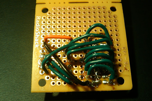
I seriously underestimated how much wire would be coming into this box. There is a Cat5 cable from the Joystick, two from the Data Entry Keyboard, one from the Left Panel, one from the Center Panel, one from the lid buttons and one from the Liquid crystal. Making the final connections on the Arduino Mega was quite challenging...a much larger box and a Mega screw shield would be much easier...
I also built a 6 volt regulator for the Arduino, which kept all the 12v wiring out of the box. All 12v wiring for the button lamps, siren, and strobe is hidden behind the removable panels.
For the Arduino folks in the crowd...check out this list of pin declarations...I think I used EVERY digital I/O pin on the MEGA - I still have some PWM outputs and some analog inputs remaining...
//WaveShield Pins
//....................2
//....................3
//....................4
//....................5
//analog outputs on PWM pins
#define GAUGE_ED 8
#define GAUGE_LR 9
//Analog Inputs
#define SWITCH_KEYPAD 0
#define JOY_UD_POT 8 //WHITE-BLUE
#define JOY_LR_POT 9 //WHITE-GREEN
//DO NOT USE - Reserved for future I2C or interrputs
//
//....................20
//....................21
//digital inputs
#define BUTTON_RED 22 //WHITE-BROWN
#define BUTTON_YELLOW 24 //GREEN
#define BUTTON_GREEN 26 //WHITE-GREEN
#define BUTTON_UP 28 //WHITE-BROWN
#define BUTTON_DOWN 30 //BLUE
#define BUTTON_ENTER 32 //WHITE-BLUE
//digital outputs
#define LAMP_RED 23 //ORANGE
#define LAMP_YELLOW 25 //WHITE-ORANGE
#define LAMP_GREEN 27 //BLUE
#define SIREN 29 //BROWN
#define STROBE 31 //WHITE-BLUE
//Keypad Col Pins
//....................34 //WHITE-ORANGE
//....................36 //ORANGE
//....................38 //WHITE-GREEN
//Keypad Row Pins
//....................33 //WHITE-BROWN
//....................35 //BROWN
//....................37 //WHITE-BLUE
//....................39 //GREEN
//....................41 //BLUE
//shift.in from joystick
#define SHIFT_CLOCK 40 //ORANGE
#define SHIFT_LATCH 42 //GREEN
#define SHIFT_DATA 43 //BLUE
//LCD pins
//....................44
//....................45
//....................46
//....................47
//....................48
//....................49
//WaveShield SPI pins
//....................50
//....................51
//....................52
//....................53


