I bounced around today, working on things as I figured out what parts went where. I'm sure it took much more time than it needed to, but it was fun anyway.
Today's work was on 4 major subsystems:
1) RAMPS electronics
2) MakerGear Stepper Plastruder
3) EndStops
4) Heated Build Platform
Remaining work:
1) Servo wiring
2) Hot End build & wiring
3) Heated Print bed thermistor install
4) RAMPS mounting
5) Power supply setup & connections
6) Use the green high-temp wiring for the heated build platform. Oops.
7) Pull the $#*$ X-idler and put in the rear fine adjustment screw I missed.
Tons of pics below, with brain-dumps in the comments for now. I need to help improve the community documentation soon, these brain-dumps will help.
RAMPS - I started the RAMPS build a few weeks ago. Someone else was taking pics, so I don't have the beginning shots...
 |
| This is where I'd stopped a few weeks ago... |
 |
| Soldering the Pololu drivers - no, I wasn't following the instructions here, I had other things to finish on the RAMPS board, but I figured this was some easy soldering to get out of the way... |
 |
| Another Pololu... |
 |
| Look |
 |
| Added the caps... |
 |
| Adding the MOSFETs |
 |
| Adding the fuse. I DID NOT install the optional diode. |
 |
| Add caption |
 |
| I pulled the jumpers & did lots of continuity testing looking for bad soldering... |
 |
| Installed on the MEGA... |
 |
| The MakerGear RAMPS kit (the 3 1k resistors are for the endstops, oops) |
 |
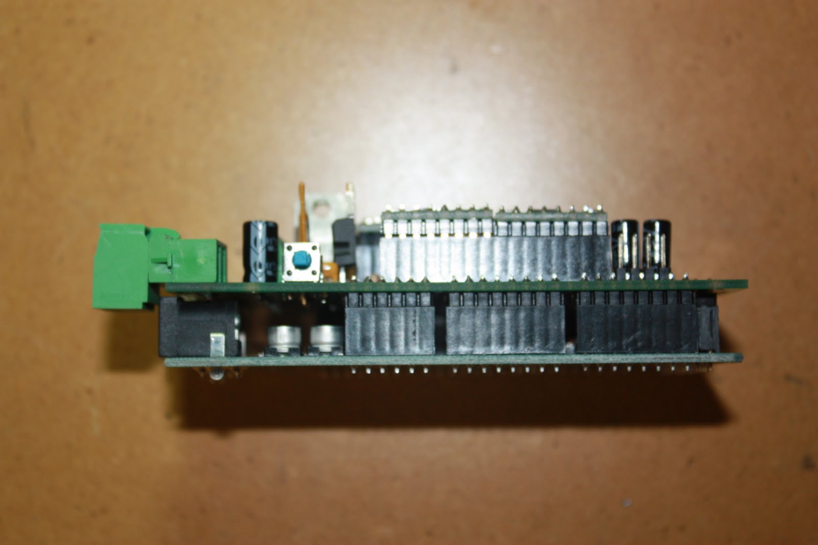
| Fully populated RAMPS and a bare RAMPS board... |
 |
| Adding the heatsinks provided by MakerGear |
 |
| Yes, I did debate heatsink orientation with myself for a minute or two... |
 |
| All heatsinks installed... |
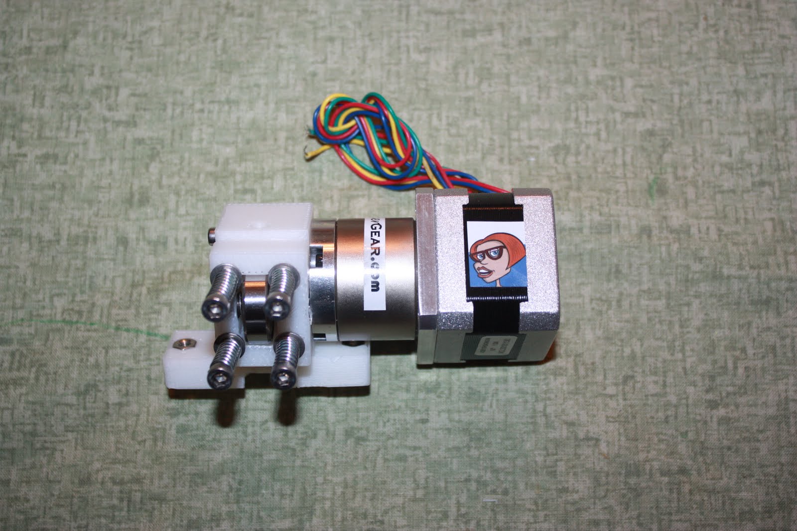
MakerGear Stepper Plastruder
 |
| My stepper extruder motor was backordered, thats why it isn't shown here. Luckily someone VERY COOL loaned me one until mine gets here... |
 |
| Example of the print quality for some of the RP parts. Not great, but should be functional. Gives me something to print later... |
 |
| I guessed on this part... |
 |
| Hope this is right :) |
 |
| Once I built it to this part, I had a MUCH better understanding of how it worked. I was so used to seeing WADE'S extruders, I couldn't quite figure out what was happening in the pics... |
Endstops - this was a bit of a puzzle figuring out what went where...by using the pics and pestering MG|Rick, I think i've got it...yesterday's build pics show the locations of the RP parts on the printer, these are mostly closeups of the mounting / wiring...
 |
| I cutoff about 4" from the endstop wires. Cutting off nicely crimped connectors pains me, but this seemed like the right thing to do. I then tinned & soldered the bare wire directly to the microswitches. I found the wiring notes here: |
http://groups.google.com/group/makergear/browse_thread/thread/d8c926dc96f6b98d?pli=1
 |
| I used shrink-tubing and the heat gun to clean up the connections... |
 |
| I will use approx 2.3 million wireties before this thing is done. I tend to be obsessive with wire routing - too much time running wire with my buddy Lou who likes the wires nice & tidy :) |
Heated Build Platform - this took some time. I REALLY should have traced the holes for the platform before I built the Y-Carriage. Oh well.
 |
MG|Rick - "socket -> board -> spring -> nut -> space -> nut -> carriage -> nut"
My version - "socket -> board -> washer -> spring -> washer -> nut -> space -> nut -> carriage -> nut
Later, when I asked, the nice locking nylon nuts are in the kit for the build platform. |
 |
| I'll switch to the nylon locking nuts later... |
 |
| Always good to make polarity OBVIOUS |
 |
| Remove the tape covering over the solder pads |
 |
| My FIRST surface-mount soldering! |
 |
| Those LEDs were NOT easy to hold in place while soldering! |
 |
| I went with the suggested plan of an LED that lights with either polarity. I think I'll swap out the reverse polarity LED later with a RED one, but its good for now... |
 |
| [Replace image once the high-temp green wire is used] |
 |
| [Replace image once the high-temp green wire is used] |

 |
| [Replace image once the high-temp green wire is used] |
 |
Shrink tubing is good. A little red electrical tape indicating the positive wire can't hurt either :)
[Replace image once the high-temp green wire is used] |
 |
I used two sizes of shrink tubing to make a nice jacket for the connector.
[Replace image once the high-temp green wire is used] |
 |
| [Replace image once the high-temp green wire is used] |
 |
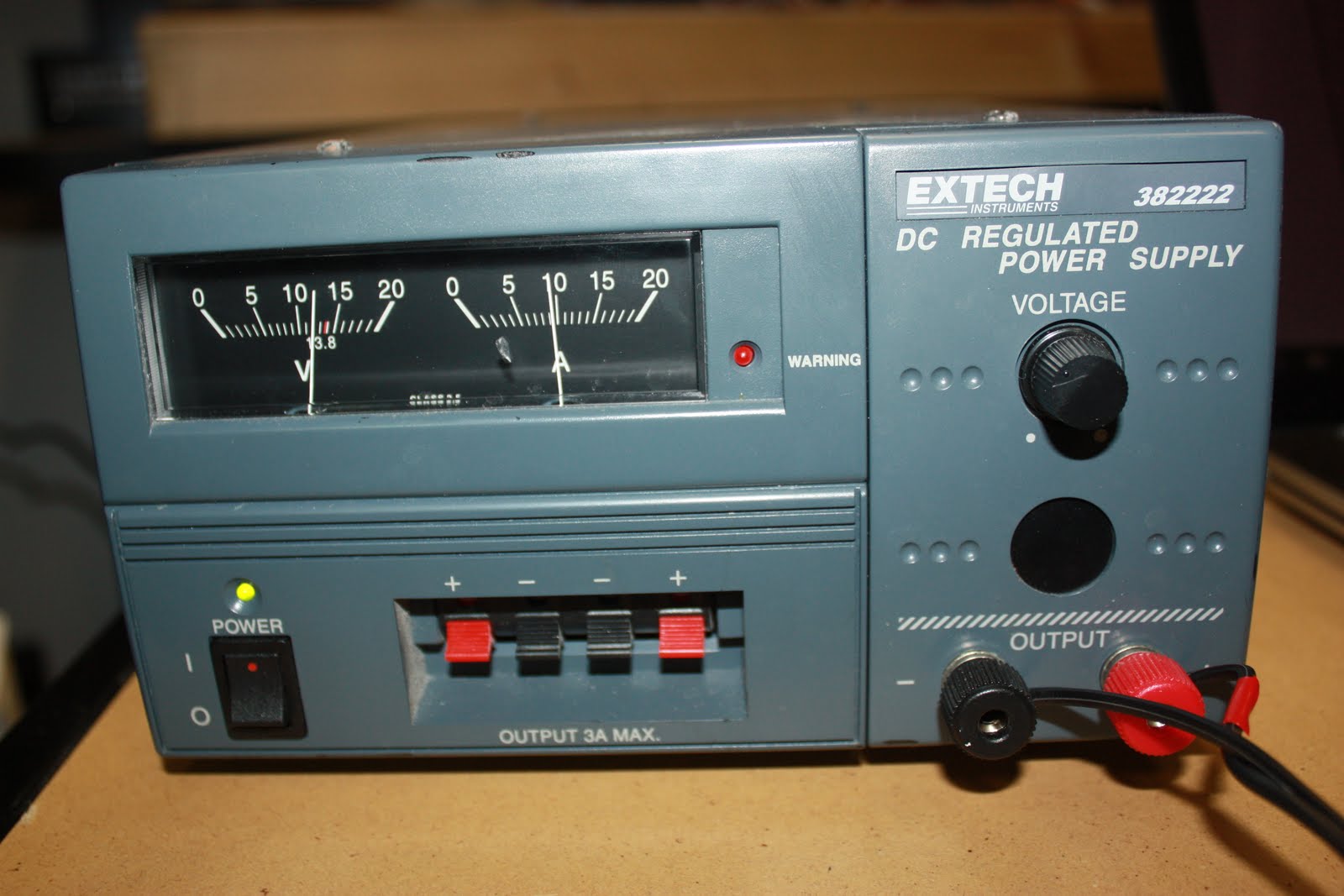
| A quick bench test - the heated print bed pulling approx 10A at 12v. It warmed up quickly. I didn't get out the temp probe, I just let it get too hot to touch and unplugged it... |